

Updating the Electrical Service
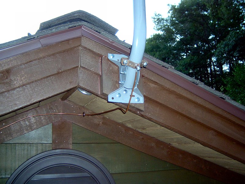
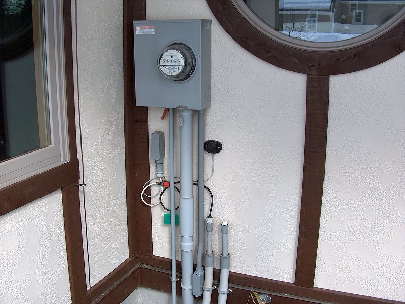
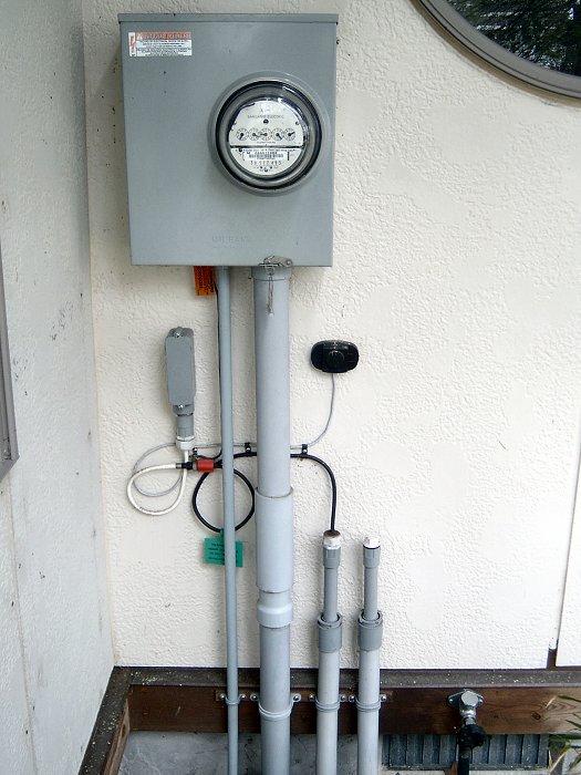 Exterior electrical goodies (2 photos).
As described in the mechanical systems introduction, the wiring was in pretty bad shape when we bought the house. I was going to have to replace everything, which I was actually looking forward to doing. Back in my wrenchin'-on-cars days, I was the "electrical guy" for the shop then I later opened my own business building electric cars, so I enjoy tinkering with wiring. Household wiring isn't too terribly difficult, so I planned to do all circuit design and the wiring installation myself. Homeowners are not allowed to make the connection from the pole to the meter and panel however (which is fine with me), so we would have to find an electrician to get the panel installed. The original plan was to have the local electrical inspector (who's also an electrical contractor) do the service panel installation, since he had done the wiring for the septic system effluent pump and said he'd do the panel as well. I played phone tag with him for a while but wasn't getting anywhere, so I talked to the plumber for a recommendation of another electrician. I figure it's a good idea to not upset the electrical inspector, so I let the him know we were going to find someone else to do the job, and he actually called back to say that was okay with him (I think he was relieved to not have to deal with me and this junky old house). The new electrician contacted us right away, and after some discussion of price and timing, we decided to have him install a new 200 amp service.
One of the first things we had to address with getting the new electrical service installed was trying to figure out where to locate the new panel. The pole is near the center of the lot, and there's no power anywhere near the back of the lot. Our only option was to bring the power in the front of the house someplace. The existing service was hanging off the rotted barge rafter (the outermost rafter of the roof overhang) between the main house and the old screen porch. I'm pretty sure the original service was installed before the screen porch was added (since there was no power in the porch), and we couldn't put it back in the same spot (code doesn't allow overhead service to go over the roof). If I'd have run the power to some other part of the front of the house, that would have meant the panel would be back in the living room our in our bedroom. The power was going to have to go into the entryway somehow, which would have meant wires coming into the house with some huge mast thing sticking up right next to the front door. In order to put the panel where we wanted, we decided the best option was to install an underground service.
Getting the dominoes lined up to have the underground service installed and the new panel put in took a little time and prep work. I needed to demolish the old wall and window framing where the panel was going to go, and get the new wall framed for the panel. I had to have siding up on that section of wall for the meter box, and get the panelling stripped from around the old service panel so we could tie it to the new service. I also had to ensure the electrician, excavator and electrical inspector we're all ready to jump at the same time, since we were living in the house and didn't want to go without power for days on end. It didn't work out exactly as planned, however.
The Saga of the Service Panel
Fun with Contractors: Fall 2005
I worked on rebuilding the porch and getting the section of wall ready for the new panel in Fall of 2005. The electrician called and
said he'd had a cancellation, so he'd be here in a couple days (rather than a couple weeks as planned). I called my septic guy
in a bit of a panic and left a message saying we needed the service trench as soon as possible, since the electrician was on his way.
He didn't call me back. The next morning I awoke to the sounds of machinery outside and there was George, sittin' in his backhoe,
chompin' on a cigar. He'd driven the thing to our house from his shop. He swung the cab door open and shouted "Where d'ya want it,
Rock-boy?" I sorta waved a vague line from the pole to the corner of the porch. He nodded, shifted the cigar stub a bit, swung the
door shut and got busy. I stumbled back into the house for my first hot cuppa Joe, and by the time I returned George was finished
and on his way up the street. One of a kind, that guy.
The electrician showed up the next day with conduit and the new panel, and installed the panel and three conduits for telephone, cable TV and power. He then added a big hunk of 8/3 NMCB inside the house from the old panel to the new so I could start getting new circuits installed - which I didn't care about at that time - I wanted that overhead wiring gone so I could work on the roof. The old meter and overhead wire were still there, so we were stuck with the cable in the living room until I could get the wall ready for the meter. He said to call him when it was ready and be right over to finish it up. I believed him. Apparently I hadn't learned my lesson from the bad experience we'd had with the landscape contractor.
I finished the wall prep and was ready for the panel in about a week, so I called and left a message with the electrician. I'm not sure how some of these guys stay in business. I've worked in the service industry as an auto mechanic. I've owned my own business. Rule number one was always answer the phone. In the construction trades I think "answer the phone" might be somewhere between wiping their feet before coming in your house and cleaning out the cab of their truck on their list of priorities... it just doesn't happen. I've figured out that the only way any communication takes place with these guys is through their Nextel 2-way. If you're one of the select few that have their 2-way number, then they'll immediately answer your "chirp" (especially if they're in the middle of a conversation with a client). Without the 2-way, you're not worthy of their time. They only get new clients when some other contractor chirps them on the 2-way and tells them about a possible sucker they can screw over a customer in need of their services. Okay, I'm calm. I'll continue...
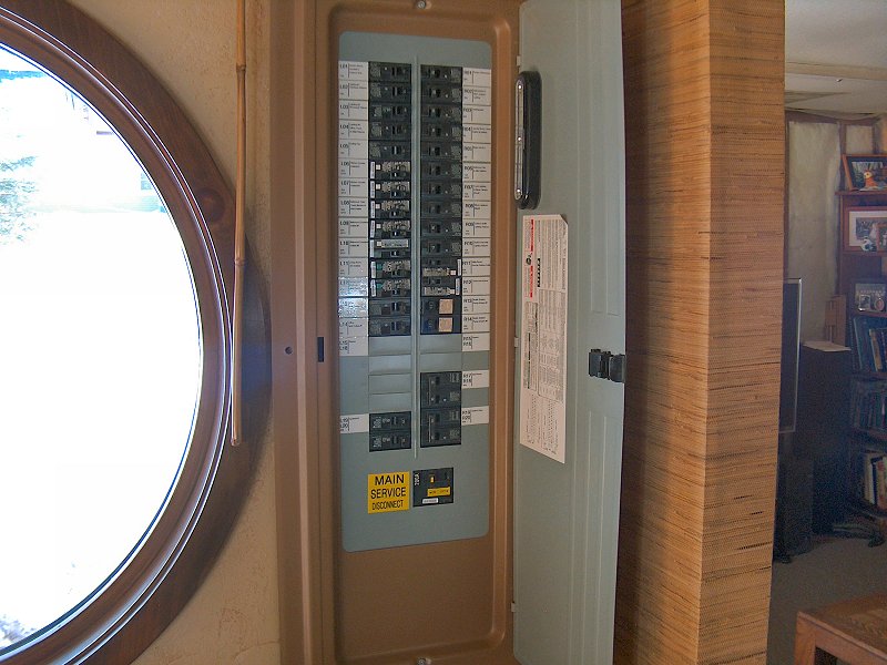
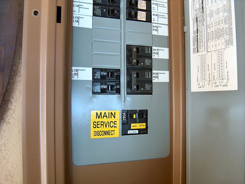
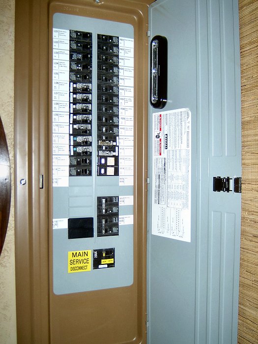 The new panel was worth the wait.
After the first few daily calls with no response, I decided I wouldn't get anywhere by being a pest. I switched to leaving a message once a week, in hopes that he wouldn't find that too bothersome and come finish the job (he hadn't been paid for anything after all, so I assumed he was interested in getting paid for the materials at the very least). Nothing. After a couple months , I cut back the calls to once every two weeks, and started to try and figure out how I was going to get another electrician to come finish the work this guy had started. After months of steady messages with no return calls, the electricians truck rolled up in the Spring of 2006. He hopped out and started feeding cable through the conduits without even a knock on the door. We didn't engage in a lot of friendly chit-chat (and there was no apology for the delay). He installed the meter and tied it to the new panel, then much to my surprise he went up the pole on a ladder and tied the new power to the old overhead lines and snipped off the old lines to the house.
As he was loading up the truck to leave, I confirmed the price with him, and asked if a check was okay. It was not. I was then informed that the price was a special discount since I was a friend of a friend (naturally), and that he would need to be paid in cash. This guy came highly recommended, and did a very good job (when he actually showed up). He's even been featured on "This Old House" when they were doing a local renovation. I had no problem with the quality of work he performed, but I couldn't get past his troubles with using his phone... perhaps he didn't know he could flip it open and push the number keys to initiate a call, since he'd only ever used the push-to-talk button on the side. Poor guy. I told him I didn't have the cash on me, since I didn't know he was going to come and do the work that day (I took a little shot there, but either he didn't understand it, or chose not to acknowledge the comment - I tend to think it was the former). I told him I'd give him a call when I had the cash so he could come pick it up. Mwuahaha.
I got the cash from the bank the next day, but didn't call him. When the lovely bride got home from work and asked if I'd paid the electrician so we could finally be done with him, I said "Nope - didn't call him either". She wasn't pleased, but I would have my revenge! This fellow blew off my phone calls for over 6 months , when all he had to do was let me know he was on another job, out of the country, his grammy had passed - whatever... just some form of communication would have been nice and I'd have some idea of when we'd have the new power hooked up. I had decided that if he was going to make me wait 6 months, I was going to make him wait a while for his money and see how he liked it. She didn't approve, but I insisted we hold for a month at the very least, and she relented. Every night between 5 and 6 pm for the next 30 days, we'd get a phone call from "Unknown Caller" (he obviously Caller ID blocked his cell number). On night 31, I answered the call, and said he could come get the cash the next day, as if no time had passed at all. He was happy to act like nothing had happened, so I did the same and handed him the cash the next day (I put it in a crumpled up brown paper bag for added effect).
Our new panel was in and all was right in the world. I got a call the next day from the electrical inspector saying the electrician had contacted him and that we were good to go. He came and signed off on the panel install, I set up the time and date for the utility guys to come and do the permanent tie-in at the pole, and a few weeks later the job was done at last.
The final chapter to this whole saga occurred in the Summer of 2008, and it's so ridiculous it's funny. One fine day I was working in the temporary shop in the driveway when our electrician pal pulled up in his truck. I hadn't spoken to or thought about this guy for over 2 years, yet here he was. We shook hands and exchanged pleasantries, and he commented on how well the place was coming together. I had no idea why he was here, so I rather awkwardly asked what brought him by. "Oh, I got your message that you needed something or other done with the new panel" he said. I couldn't help myself and laughed out loud. I told him I'd left those messages two years ago! I don't think he believed me, but we both had a good laugh about it and he hung out for a while to have a look at the changes inside the house since the last time he was here. All's well that ends well, I suppose.
Wiring Plans
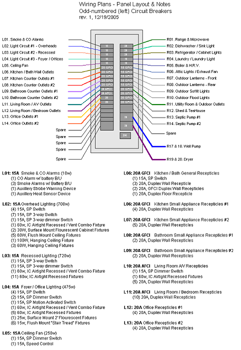 Planning started with the panel (2 sheets).
Making Plans: Winter 2005
I completed the wiring plans in Winter of 2005, having worked on them for a month or two while waiting to get the new service
installed. I think the old mess of wiring that was originally in the house helped drive my desire to try and create an ideal
wiring system for the renovation, since I had a very good idea of what I didn't want to end up with. The idea was to have
plenty of receptacles in every room so we'd never need an extension cord or power strip, as well as lights and switches located
where they'd make sense. A couple issues I especially wanted to address were the lack of attic lighting and outdoor receptacles that
we'd suffered through with the old system. I also wanted to ensure plenty of power would be available in the kitchen and the bathroom,
via multiple circuits, so we wouldn't have to deal with our old "don't make toast when the coffee maker is running or using the hair dryer"
scenario, which would pop the fuse in the old days.
I started the electrical layout with the service panel plan, and tried to put in whatever circuits I could imagine needing for the
completed house. We had also decided what appliances we were going to outfit the kitchen with by this point (although we hadn't bought
them yet), so I was able to download the installation instructions and verify the power requirements for each of those while doing the
planning. I didn't worry about switches and receptacles at that point, and just dreamed up whatever I thought might be useful
then made a spot for it in the panel. With a notion of the number of circuits I'd want, I then tried to balance the power distribution
across both legs of the service panel. Next I started working out where I was actually going to place lights, switches and receptacles,
and totaled up the power requirements for each circuit while adjusting the distribution of circuits in the panel. Working off a
tentative house plan with the service panel schematic as a guide I layed out wire runs, and tried my best to minimize the number of
junction boxes (especially under the house) while providing adequate power and light to each room. I must add that a great deal of
the wiring layout was based on the information in Rex Cauldwell's
Wiring a House ![]() from Taunton Press. Cauldwell not only clearly explains what is required for safe household wiring and why, but he also makes a lot of
what he calls "above code" recommendations based on his years in the industry. A highly recommended read for anyone planning to do some
household electrical work.
from Taunton Press. Cauldwell not only clearly explains what is required for safe household wiring and why, but he also makes a lot of
what he calls "above code" recommendations based on his years in the industry. A highly recommended read for anyone planning to do some
household electrical work.
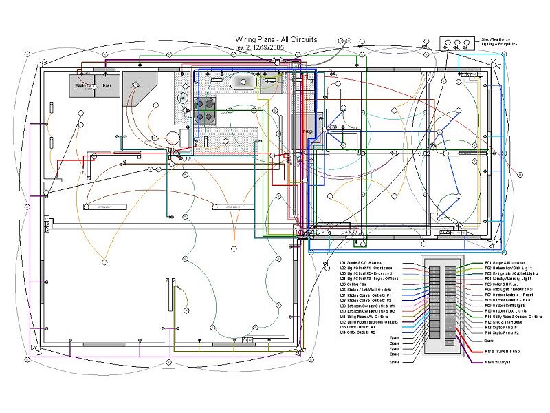 The completed wiring plan.
The wiring plans have been extremely useful, and I'm very glad I took the time to get them worked out early in the project. Nearly every wall has some wiring in it, so having the plans finished before any carpentry work began has helped avoid the need to tear any new work apart because I neglected to get the wiring in place first - almost. I somehow completely missed the air conditioner circuit, probably because I was working on the wiring plans in our 60° barely heated house in the middle of Winter. I did place extra runs of 12/2 in the walls before I installed the GWB around the panel, but as we shop around for efficient A/C units, it's looking like I'm going to need to get a piece of 10/3 in there to supply adequate 220v power to the A/C unit. I think I can thread the wire into the wall from under the house without having to tear out drywall (and here I thought I was finished under the house), so it may not be too bad.
Updating the Wiring Plans: Late Summer 2023
The last couple years have had a lot of significant renovation work progress made in the living room, bedroom, and walk-in closet/laundry room.
Most of the rough carpentry work for those spaces is now complete, which also allowed the last of the wiring to get taken care of. While working on
that wiring installation (additional light fixtures, wall plugs, etc.), I found that the original wiring plans were becoming less and less
accurate. I finally determined I needed to go through them all and ensure they properly reflect the physical wiring that has been installed, which
pretty much required changes to every page of the 30 pages of plans (although for many of the circuits, I merely moved the washer & dryer
from the North wall to the East wall of the laundry room). I'll eventually need to go through the layout for each of the banks of breakers in
the service panel and update all of those as well, but at least that information is now correct on each of the circuit plan pages. The new plans
are listed in the Mechanical Systems Data section of the Specifications page,
and I've also included a link to the Individual Circuit Plans ![]() here for reference.
here for reference.
Household Wiring Installation
New Wiring, Switches, and Plugs: Spring 2006
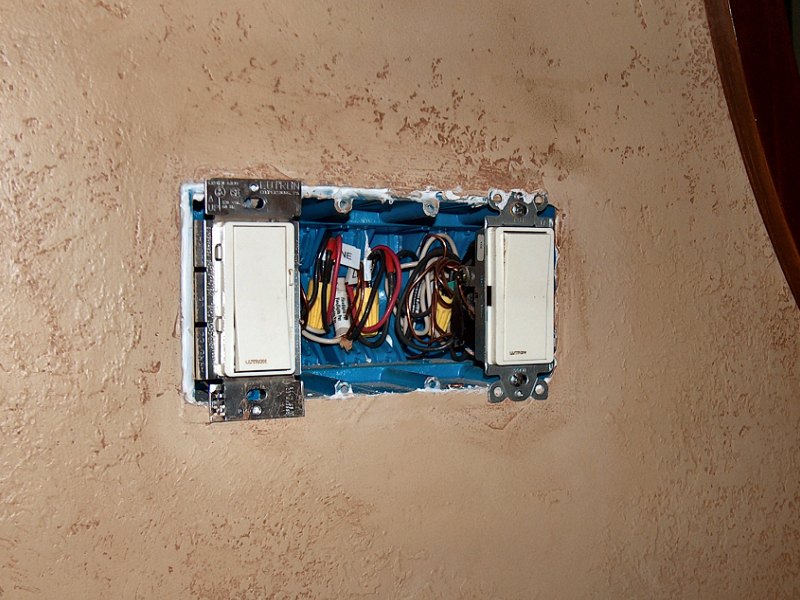
Before drilling holes in studs and feeding wires, we had to decide on colors and styles for switches, receptacles, electrical boxes, and all
the rest of the stuff needed to make the light come on when we flick the switch. Because we live here while the renovation is happening
we couldn't just run all the circuits then wait until the finish work in a particular room was done to install the fixtures - I needed to
disconnect the old circuit and be able to use the new one pretty much on the same day - which meant the switches and receptacles had to be
on hand. As with most of the mechanical systems supplies, you get what you pay for with this stuff so we decided early to eliminate the bottom end
stuff from the mix. I couldn't see putting in the effort to re-wire the house only to have switches fail and plugs falling out of the wall because we
wanted to save a couple bucks on supplies. I made a few trips to the store to get an idea of what was available and take some notes, then planned
a hot date with the lovely bride to the Home Depot electrical aisle (I'm so romantic). She agreed that the 89¢ light switches were not
acceptable, and we moved on to the higher-end stuff. After much flicking of sample switches, we decided to just go for the best and
use Lutron®
![]() Designer Style lighting controls in
Light Almond for the entire house. We selected their Diva® and Maestro® lines
for dimmers and fan controls, the matching Claro® line for regular light switches and receptacles, and
decided to finish everything off with screwless wall plates.
Designer Style lighting controls in
Light Almond for the entire house. We selected their Diva® and Maestro® lines
for dimmers and fan controls, the matching Claro® line for regular light switches and receptacles, and
decided to finish everything off with screwless wall plates.
 The wiring kit & PT-1600 labeler.
As I started to add up the costs for the switches and receptacles we were going to need, I had some doubts about our decision since a basic dimmer was going to run $20-$30 each (with some of the three-way units topping $75). We stuck with the decision on switches (and I'm glad we did), but decided we could skip the designer style wall receptacles and just use normal stuff for the units that wouldn't be located at counter-top height (the $5 ones, not the 89¢ junk) . As we've gotten closer to finish work in the kitchen, we also decided to go with black controls and stainless-steel wall plates to better match the appliances, rather than light almond stuff. Because of the relatively high cost of all the lighting controls, I did some poking around on the 'net and found I could save a significant amount of money by purchasing all the units online, rather than from local stores. It takes a little while for the stuff to show up (since it's just getting processed by the online retailer and then shipped from the manufacturer), but the cost savings is worth the wait - online costs were less than half the local prices, even with shipping.
In addition to selecting the switches and receptacles before work could begin, I also selected the heaviest, largest electrical boxes available for use in the walls. The cost difference between the tiny, thin-walled boxes versus the heavy-duty units is insignificant compared to having a roomy, solid box for wiring that the screws won't pull out of the first time you snug up the light switch in the box. I also put together a little "home wiring kit" of tools and supplies to allow me to work without constantly having to go find more wire nuts or staples in the middle of the job. Finally, the most important item needed to install household wiring, in my opinion, is a label maker. No matter how nice the plans are and how good you think your memory is, everything should be labeled throughout the wiring project. I used a Brother P-Touch® PT-1600 handheld label-maker when I was doing data center wiring in my IT days and loved it, so I purchased the same unit for use on the house renovation. Apart from the obvious need to label the breakers in the service panel, I labeled the ends of wire runs at the wall and junction boxes, as well as inside the panel itself. This was especially helpful for our project since many of the new circuits were not connected until months (sometimes years) after they had been put in the walls and ceiling during the installation of the new panel. I also labeled the cover plate of every junction box with the breaker number for the wiring inside, as well as the back of the wall plates for any receptacle or switch. Before doing any electrical work, it's now a simple matter of pulling the wall plate (or looking at the junction box in the attic) to see what breaker to switch off prior to exposing the wiring.
Household Wiring Completed (mostly): Early Fall 2023
While most of the wiring work was done in 2006 during the initial demo and renovation work, a couple circuits for interior wall outlets and some
lighting remained incomplete until I was able to finish the interior rough carpentry work. With the work to level the ceiling joists for the
living room and bedroom, then re-build the bedroom and walk-in closet/laundry room walls finally taken care of (nearly 20 years later),
I've also managed to get the last of the interior wiring wrapped up at long last. This final wiring work included installation of all the lighting
fixtures for the living room, bedroom, and closet, the remaining wall outlets for the bedroom and laundry room, and finally the last of the inter-connected
smoke alarms.
The reason I say it's "mostly" done is because there remains a couple things to take care of, and I doubt I'll get to those this year — There's one more outlet to install in the living room, which will either get a floor outlet or get installed within a post near the center of the space, (the 12 ga. wiring is in place under the floor and waiting for the outlet already). I've also got a couple more outdoor lights I want to install in both the front and back yards, but those also have the outdoor-rated cable in place and are just waiting for the lanterns to get made. So I'm fine with saying the wiring is completed at this point, even though it will need a little more tinkering eventually.
Household Wiring Upgrades
The KesterHouse Gets "Smart": Summer 2022
We picked up an Amazon Echo Dot (2nd Generation) back in 2018, and enjoyed having little chats with Alexa to occasionally get weather
forecasts or Red Sox scores, but didn't do much else with it. That changed in 2021 when I finally picked up a little "smart plug"
adaptor for the TV backlight, so I didn't have to wander to the back of the TV to turn it on and off. We also started changing out many of our
recessed Halogen light bulbs for LEDs as the prices for those have come down (to the
point where the LEDs are much cheaper than getting replacement Halogen bulbs these days). However, there were some problems as a result
of changing from Halogen to LEDs: the bulbs wouldn't dim down very well, they'd sometimes flicker when dimmed, and other times they'd glow even
though the switch was off. As mentioned above, we didn't skimp when we installed new light switches and dimmers, going with all
Lutron® Diva® switches, and even a few of the pricey Maestro®
dimmers. It's been over 10 years since most of that wiring was installed, and it seemed many of those original switches and dimmers didn't like
to play nice with the new LEDs. After a fair amount of online research, it was looking like our switches and dimmers needed an upgrade. We've
been very happy with the Lutron® stuff, but I wasn't too keen on spending the bucks to just change to newer
versions of all the same switches we already had installed. Based on the information I'd been reading, upgrading to "smart" Wi-Fi enabled
switches and dimmers would probably take care of any LED control issues. Another contributing factor to this decision was that we finally
joined the 21st century, and actually got our first smartphone last year (an Apple iPhone SE II, through a too-good-to-pass-up deal
from Comcast). With a smartphone available to run an appropriate app remotely, we decided to take the plunge and start swapping the
old switches and dimmers to new "smart" switches throughout the house.
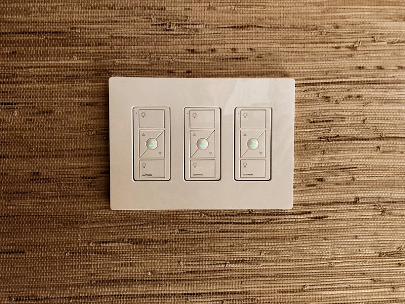
 Installing Lutron® Caséta® switches & dimmers (4 photos).
I had looked at a load generic Wi-Fi enabled switches, but I was drawn back to the Lutron® stuff again, and it would be nice to keep the same screwless Claro® wall plates for everything as well. Most of these other switches would work fine with Alexa, Google Assistant, or the Apple Homekit, but I wasn't thrilled about having a bazillion additional devices all connected to the wireless network, competing for bandwidth with everything we already had going. That's pretty much what sold me on the Lutron® Caséta® set-up: it runs on its own dedicated network with their "SmartBridge™" device. The SmartBridge™ is then hardwired to the router so other Wi-Fi devices can access it through the home network, but the wireless connection to all the wall switches is on the Caséta® private network. It was all looking good, but it's awfully expensive stuff (about $60 for the basic Caséta® dimmer or switch, compared to $35 for the Maestro® dimmer).
Before we got the bridge and a handful of switches, I picked up a single Caséta® PD-6WCL dimmer to verify how it would work with the LEDs. Installation was simple enough, and we tried it out on the 4-inch kitchen task lights. The dimmed flickering was gone, and when the switch was off there was no longer a little glow from the bulbs. Another really nice feature is the ability to adjust the "low-end trim" and "high-end trim" for how the dimmer works. You turn the lights off, then press and hold a couple buttons on the thing to enable adjustment mode. You then tap the dim up button once to check the light output. If you want it a little brighter or a little dimmer, just fiddle with the buttons and set it exactly where you want it. You can then do the same thing to set the maximum brightness, then put the switch back in normal operating mode when you're satisfied. We were sold — after months of frustration with how the LEDs were performing, upgrading to new switches was going to solve the problem.
I then purchased the Lutron® Caséta® SmartBridge™ PRO2, along with another PD-6WCL dimmer and Pico remote dimmer (with nightlight) for the 6-inch recessed lights in the kitchen and living room. These lights are wired with a pair of 3-way switches, but the way all the Caséta® switches and dimmers work, you no longer need the additional switches for a multi-switch set-up. The additional switches may be left in place, assuming everything was wired correctly initially with a neutral wire and a 3-way "traveller" wire. However, the thing I thought would look a little odd with that option is that other switches in the same multi-gang wall plate will eventually be replaced with Caséta® switches, which would then leave a mix of Caséta® "flat" switches and the old Diva® paddle switches. To make the paddle switch go away (and not leave a blank spot in the wall plate), Lutron® also has a "Pico wallplate adaptor" which mounts to the gang box and allows the remote to take the place of the paddle switch. I got the new dimmer installed to replace the old Maestro® dimmer in the kitchen, then replaced the switch at the other end of the 3-way pair near the bathroom with the Pico remote and wallplate adaptor. The SmartBridge™ PRO2 (which is nearly twice the cost of the standard SmartBridge™, but can "talk" to a lot more stuff) was placed in the attic between the entrance and the main room to provide the best possible coverage for the entire house (mentioned below in the Updating the Network section). I then got the Lutron® app running and added the new switches and remote to that. The Lutron® "skill" was added to Alexa, and it all worked together perfectly. We even changed out the old thermostat to a new Wi-Fi enabled Honeywell® unit that was also added to the Lutron® app.
 The last few Caséta® upgrades (3 photos).
Yes, these switches are expensive — although there are other Lutron® "smart home" systems like the RA2 Select, Radio RA3, or Home Works, with costs that are crazy. For our little 1,000 square foot house the Caséta® stuff will do the job nicely. I'll need one of the PRO dimmers (twice the cost of the regular Caséta® dimmer) for the outdoor "perimeter downlights" to handle that load, but everything else will be standard dimmers and switches, most with Pico remotes and wallplate adaptors to replace existing 3-way stuff. We're not buying all this stuff at once, and instead spreading it out by picking up a single switch, remote, and wallplate adaptor each month, more or less. We'll probably have all the switches replaced by the end of the year.
The Last of the "Smart" Switch Upgrades: Early Fall 2023
Okay, so we didn't get all the switches done last year, but given how long it usually takes me to actually finish a project, this will do. As
mentioned above, the final bits of rough carpentry work were taken care of this Summer, which allowed me to get the rest of the household wiring
completed as well. For this most recent wiring, we also just went ahead and used the Caséta® switches for many
of the lights (and I did install all the correct 3-way wiring for the light fixtures, even though the Caséta®
switches don't use the 3-way stuff for multi-location switching).
One more thing that deserves mention regarding this Caséta® stuff is the usefulness of their "Weatherproof+" outdoor on/off plug unit. We picked up one of these things last Fall to operate our plug-in Jack-o-lanterns for Halloween, and then our holiday lights for Christmas. The reason I mention it here is because it also make a very handy "range finder" to determine the coverage of the SmartBridge™ unit that communicates with all the Caséta® switches. Usually a Caséta® switch is hard-wired in place and tested, then it's added to the Lutron® app for remote control. However, with the plug-in thing it just needs to be powered/plugged in to be added to the app. After that's been done the first time, it may be unplugged and moved to wherever then plugged in again, and then the app can be used to see if it's still within range of the SmartBridge™. This worked out very well to check to see if the tea house and garden shed were within range of the SmartBridge™, since it would be really nice to be able to control the floodlights on those outbuildings from within the house. I was pleasantly surprised to find that both buildings are covered (I guess putting that SmartBridge™ in the attic did the job). That allowed adding a Caséta® on/off switch in each building for their respective flood lights, and I also added a Caséta® dimmer in the tea house for the tokonoma recessed light.
The final replacement was to swap the old Lutron® DVFSQ-F 3-speed ceiling fan control for the Caséta® PD-FSQN 4-speed control switch in the genkan. That completed all switch upgrades, with a total of 18 new Caséta® switches, along with seven Pico remotes that replaced 3-way switches, and then the "Weatherproof+" outdoor on/off plug unit. We still have a few standard light switches and a couple standard dimmers in a few rooms where we can't justify a Caséta® upgrade, but the majority of our lighting may now be controlled with the app or a voice command. The total cost for all the Caséta® gear was nearly $1,800, but getting flicker-free, fine-tuned dimming control of all the LEDs (along with the convenience of simple voice commands) seems worth the expense, and we're very pleased with the results.
Voice & Data Wiring Installation
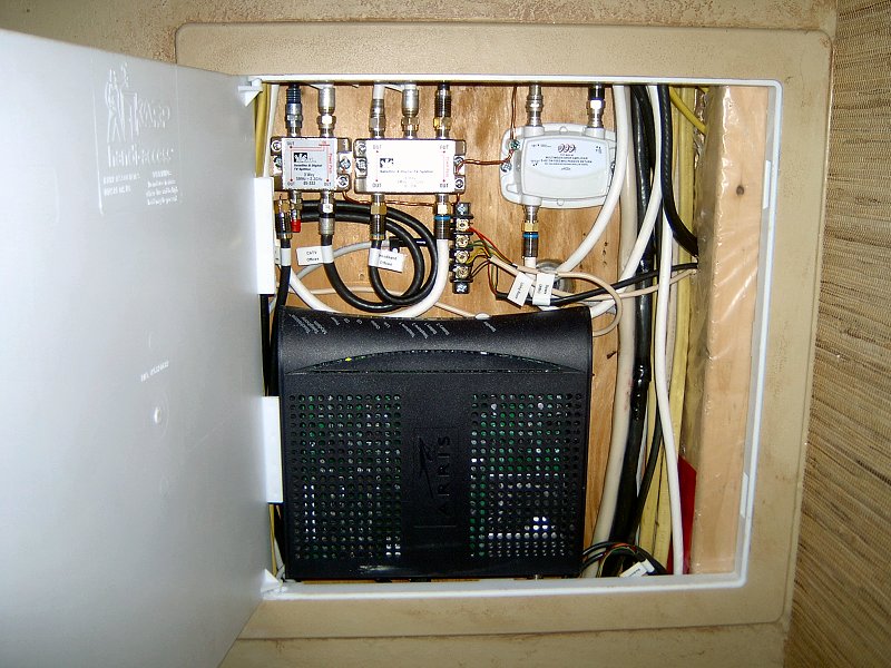 The voice & data wiring access.
Planning for the Future?: Early 2007
While installing the wiring for switches and receptacles, I also tried to get everything in place I could think of to meet our needs
for home networking, home entertainment, telephone and CATV. Looking back now on what I managed to get installed, I would have done
a couple things differently on the home networking end, although the latest wireless tech has resolved any shortcomings of the initial
installation.
I set up the voice & data wiring much the same as the household power wiring, so all voice & data runs would emanate from a central service entrance and feed various locations throughout the house. We receive telephone, internet and CATV from the same provider (Comcast), so there's just the one coax cable coming into the house near the electrical service (we did install an extra conduit in case we switch to FiOS or add some other service at a later date). I added an access panel and mounted the cable modem and all my coax-splitters inside the wall below the electrical panel. I then split the coax line from the pole to feed the phone modem, broadband modem, and CATV through another splitter for CATV distribution. The second splitter feeds CATV wall plates located in the living room, bedroom and the lovely bride's office (we only have the one TV, but we're not going to live forever, so it made sense to add CATV drops where ever they might be needed). I purchased a roll of good quality RG-6 coax, a crimp tool, and gold-plated connectors so I could custom make all the lengths of coax required for the installation. The telephone wiring from the cable modem (RJ-11 output) is connected to a junction block in the wall with the modem, where I distribute the phone lines to the same areas as the CATV, as well as a couple lines to my office. I also ran a spare phone line and healthy length of RG-6 into the attic as spares, in case we need to add another drop somewhere else.
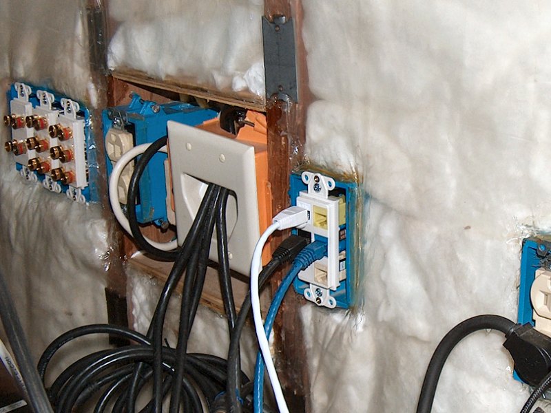
 Multiple RG-6 leads behind the home entertainment area.
I changed the configuration of the stuff in the wall behind the TV when we recently upgraded to Hi-Def (I was trying to hold off on the new TV until the renovation was done, but the 25+ year old Sony finally conked out last year) and wanted to clean up the mess of CATV signal splitters that were kicking around behind the home entertainment center. One of the problems with wall plates for coax is that they introduce additional signal loss to the line compared to just running the coax through a hole in the wall and connecting it to the back of a device. With the wall plate, the coax is terminated in the electrical box and screwed onto the back of a little adaptor on the wall plate, then another piece of coax runs from the front of the wall plate to the device. Every little adaptor adds -3db signal loss, (and every end connection in a line doesn't help either) so they can start to add up. I had tried to cram a couple 3-way splitters inside an electrical box (1 in-2 out, with one of the "outs" feeding another 1 in-2 out splitter), then connected all the outs to the back of a multi-gang wall plate with little pigtails of coax. It was ugly. I started over by losing the wall plate / electrical box combination, and went with a little double-gang wall plate that's shaped like a big louver so you can just feed wires out of the wall without having to use adaptors. The open plate is attached to a "backless" electrical box, and I mounted a good quality 4-way splitter to the wall behind the opening. I can remove the wall plate and gain good access to the splitter to screw on the coax through the double-gang opening, and I got rid of all those little pigtails of mangled coax. It's much neater and provides a noticeably better signal to the TV, cable box and VCR. I'm also planning to add a TV antenna soon, so the new configuration gives me a little room to add the additional coax drop from the attic. With all the signal splitting going on at the service entrance and behind the TV, I decided to add a CATV line amp on the coax line from the pole as well. I also added termination caps to all of the coax runs that don't connect to a device (office, bedroom, attic) to eliminate any ghosting or interference in the CATV signal.
I tried to minimize the home networking wiring in the walls, since the technology changes so rapidly it didn't make a lot of sense to install a bunch of components that would likely be obsolete by the time I finished. Even though the phone modem can also be used for internet access (it's got a pair of RJ-45 outputs on it in addition to the RJ-11 outputs), I decided to just run RG-6 coax to my office, then connect a dedicated broadband modem there and keep all the Ethernet cable in the office. I did install a length of Cat-5e cable in the wall between my office and the lovely bride's through a couple of RJ-45 wall plate connectors, thinking she could use that to connect her desktop to the network. We've since decided her office would be more of a traditional Sukiya style room, so with no desk there wouldn't be a desktop system either. The wall connection might still get used for her laptop, but most of that will be handled through wireless networking now. What I thought I should have done when I had the walls open was run an Ethernet cable to the home entertainment area. Our Blu-Ray player is set-up to have an internet connection (for additional BD Live content), and with Netflix streaming movies available, it would be very nice to have the throughput of fast Ethernet available at the TV. The problem with running wireless G networking for streaming video was it could only run at 54mbps (compared to 100mbps fast Ethernet) so the feed was pretty choppy. I upgraded our home network to gigabit Ethernet (1,000mbps) not long ago when we lost a router, and picked up a wireless N access point and bridge to connect the home entertainment goodies to the internet. Wireless N runs at 300mbps, so it ended up working out better than if I'd connected the TV with fast Ethernet in the first place (as suspected... it would have been obsolete by the time I was ready to use it). Okay, I admit I've still got some computer geek in me even after all these years of working on the house.
Updating the Network (and Audio) Wiring: Spring 2022
The wireless bridge to get networking behind the TV back in 2009 had been doing the job pretty well, but by late 2021 we were starting
to have some issues with the networking for the living room. We've had a number of network modem upgrades from Comcast over the years, with
the latest being their xFinity "xFi Gateway". This unit provides excellent 5GHz and 2.4GHz Wi-Fi for the entire house and back yard
(to the point where I no longer have my own Wi-Fi access point and router). It also has four Cat-6 Ethernet ports on the back, so it's
very easy to add my own unmanaged network switch for the rest of my computer equipment (I'm currently running a NetGear GS110MX 10-port
switch in the office). A few years ago we picked up a FireTV box for streaming, and found that it actually worked much better if it was
hardwired to the network. I also have this ancient thing called a "SqueezeBox" from Logitech, that we connected to the audio system
to stream all our music from our media server. The SqueezeBox also prefers an Ethernet connection, as does the Blu-Ray player, so in 2015
I ended up going under the house and running a pair of Cat-6 patch cords from the office over to the living room. I figured I could use
one to connect directly to the Blu-Ray, then connect the other to a switch to patch in everything else in the entertainment center. I used
female-to-female Keystone connectors in a wall plate in my office to connect these to the switch, then just left a few feet of patch cord
coming out of the wall behind the TV to connect to stuff there. The new patch cords seemed to be working okay, despite having lost
connectivity to the SqueezeBox or the FireTV once in a while. We suffered a significant lightening strike
some where out back in the Summer of 2019, which fried most of the "wall wart" power supplies in the house, and killed the home
theater receiver too. After that we didn't use the home entertainment stuff much, so I didn't pay much attention to the drops.
 The re-configured speaker connections (2 photos).
Then along came all the new streaming services, and with COVID-19 lockdowns, we were spending more time in front of the TV. First we got Paramount+ (Showtime moved "Inside the NFL" to that streaming service, so that had to happen), then I wanted to see the new Tom Hanks "Greyhound" movie, so that added AppleTV+ — which required a new FireTV stick since the old box didn't support the AppleTV+ app. Comcast added Peacock and Netflix streaming services to our CATV package, but streaming them through the xFinity set-top box was painful, so it was more convenient to run those through the FireTV stick too (for which I also bought their Ethernet adaptor to leave it hardwired). The network disconnects were getting annoying now.
I finally determined it was time to figure out what was happening with the networking for the living room while we were installing floor underlayment in late 2021. We had disconnected everything from the entertainment center to move the stuff out of the way for floor work, and I had this now massive bundle of wiring sticking out of the wall. Since that photo above of all the coax (from 2009), I'd also added wires for the outdoor speakers, a phone line, and the two network patch cords to that same opening. I decided I would re-route the outdoor speaker wires to their own Keystone wall plate with the surround speaker wires to get those out of the coax bundle, then add a new Keystone wall plate for a phone jack and the networking connections. I had gotten us a new home theater receiver after the old one failed (but haven't connected it yet), and it had more surround speaker connection options than our old one. I had also used the incorrect speaker wire for the old Keystone surround connections up to the attic, so I needed to change all that to proper CL-2 rated in-wall speaker cable (I had just used "normal" speaker wire to get the previous surround speakers hooked up).
The upgrade project began with ordering all the little Keystone adaptors for audio banana plugs and RJ-45 punch down connectors, wall plates, a small bulk roll of Cat-6, a couple rolls of 12-ga. CL-2 speaker wire, and an Ethernet cable end-crimping kit. Next I got the wall vapor barrier out of the way, then removed the wall insulation to figure out where I had run the speaker wires to the attic, as well as evaluate how much of a pain it was going to be to run new Cat-6 from the office to the living room. As I got the insulation out of wall next to the left side power box, I found that when I had originally run those new patch cords back in 2015, they had apparently not been long enough to do the job. Both patch cords were connected to a female-to-female Cat-6 connector inside the wall, which then had another 10-foot patch cord running through the wall and out behind the TV! I removed the connectors and slapped on an Ethernet cable tester — the cables from the office to the connectors were fine. I then checked the two cable from the connectors to the wall plate, and those were both fine too. Over six years of funky networking for the living room and it was because of a couple cheap-o patch cord connectors.
 The re-configured network connections.
Rather than add a new pair of female-to-female Cat-6 connectors inside the wall (which could fail again, with no access to them once the wall is finished) I went a little bonkers and snipped the ends from the cables, then actually stripped, soldered, and shrink-wrapped each of the eight conductors in the existing patch cables. I then wrapped some electrical tape around all the individual, shrink wrapped wires, then wrapped a little piece of Aluminum foil around the bundle, and shrink wrapped over all that to make a new "shielded" cable connection. With the Cat-6 runs from the office to the TV now working properly, I got busy getting all the wiring re-arranged for the new Keystone wall plates. The old speaker wire runs for the attic were removed, and new CL-2 cable was run up the walls and through the top plate on both sides of the window — right rear surround, right side surround, and right front Atmos up one side, and the same for the left speakers up the other side. To also accommodate the right and left runs under the house out to the outdoor speakers, I moved all the speaker connections to a new triple-gang box mounted at the left side of the center wall stud. The single-gang power outlet was re-located from the left of that stud into the center section (with all the coax), then a new single-gang box was added to the right side. That new box now holds four RJ-45 punch-down Keystones for networking, and one RJ-11 for a phone line (so no more patch cables hanging out of the wall). The networking connections in the new box have the two old Cat-6 runs from the office switch, with a 6-foot patch cord to the Blu-Ray player (blue) and another into a Netgear GS305 5-port switch (black). I also ran a new, white Cat-5e patch cable from a Keystone punch-down in that box up into the attic, which will connect to a Lutron® Caséta® SmartBridge™ PRO2 (I don't want to have that little white, glowing box sitting in the entertainment center, and it'll provide better coverage for the whole house if it's near the center of the house in the attic). That adds another 6-foot patch from the wall to the switch for the attic (white), with two more 6-footers from the switch to the SqueezeBox (grey), and to the FireTV stick (red). Since I had a 100-foot roll of Cat-6 I'd purchased to replace the old office runs (but didn't need for that), I also added another Keystone to the wall plate (yellow) connected to that roll, and will run that around the bedroom to add a new network drop over near the walk-in closet when I get the rest of the bedroom wiring installed.
All the networking cables were tested again and everything checked out fine (and all ends were attached using the TIA/EIA 586B pin out wiring). All the new audio lines are in place, with plenty of extra wire coiled in the attic and labeled for when it comes time to get those surround speakers connected. The new arrangement behind where the entertainment center will live is much cleaner, and should do the job nicely when it comes time to get the home theater stuff all hooked up once more. Hopefully I won't ever need to get into the wall for networking or audio wiring changes again.
One Last Tweak: Winter 2022-23
While finishing up the last of the wall insulation work for the closet/laundry room, I
also went over the vapor barrier for the living room and bedroom walls to ensure all the seams and staples were sealed. That got me thinking
about those big Boston Acoustics tower speakers we've been moving around for years, and where they're going to sit when the day comes to finally
set-up the home audio system again. I think having them just sit in front of the built-in shelves and cabinetry will be fine, but the next
residents here may not be into that... Since I still had a fair amount of the 12-gauge, CL-2 speaker wire available from when I replaced the surround
speaker wiring runs in the attic, as well as an extra electrical box and some keystone wall plates; I decided to go ahead and add a pair
of speaker wire runs to the front wall to accomodate in-wall front speakers, as this was the last time I'd have access to that wall before
starting wallboard installation.
I mounted the new electrical box next to the existing triple-gang audio box, then pulled back the vapor barrier and insulation to run the speaker wire through the existing wiring holes and up in between the wall studs on each side of the front window. The stud spacing was a little narrow in the bays right next to the window, so I went to the next bay which is closer to a full 14-1/2" wide (and more or less centered in the wall on each side of the window). I also added some rigid foam insulation within each bay to define a space 18-inches tall, with the top about 4-feet from the floor. The exact location for the speaker areas is 17-3/4" from the inside of the window casing to the inner edge of the stud for the left opening, and 19-3/8" from casing to stud for the right opening. Both openings are 38-1/4" from the ceiling underlayment. All the insulation was then replaced and the vapor barrier sealed back over everything to prepare the wall for finish work. With the new wall box and in-wall wiring in place, if we (or the next home owner here) ever decide to change to in-wall speakers for the front of the living room, it'll be a simple matter to just cut the wallboard, remove the insulation, and connect the in-wall speakers to the existing wires.
FM/UHF TV Antenna Installation
 Installation details (10 photos).
Free TV: Summer 2010
Yeah, I know - seems really silly, doesn't it? With all the wonderful options for cable, FiOS and satellite, why bother
with an antenna? Well, two reasons: 1) Picture in picture TV viewing. Comcast used to broadcast the local networks in HD
through the cable without the need for a converter/decoder box to tune in about 30-40 channels. When they upgraded
to all digital Xfinity service, they quietly dumped the network HD feeds. I can still plug the cable directly into the
TV and tune in a bunch of stations, but the stations are only available in SD (480i) which is pretty awful to look at
on an HD TV. With the antenna, I can grab over-the-air digital HD broadcasts from most of the local networks at 1080i.
It's quite handy to be able to have one picture with the Red Sox via the cable box, and another picture with the Patriots
running the over-the-air network feed. 2) FM radio listening. There's some fine music stations and public radio in Boston,
and I don't want to pony up the dough for an XM satellite tuner to pull them in to our little house. We pretty much listen
to Pandora whenever we want some music on (using a Squeezebox to get it to the entertainment system), but for those times
when we want to listen to the radio however (mostly NPR), without the antenna we just get static across the dial.
Before getting anything for an antenna, I needed to figure out how big the thing was going to have to be, and how high
to mount it. With all the hoopla surrounding the end of analog TV broadcasts in June, 2009, there are plenty of tools
available on the web to help get things worked out. One of the more useful is
AntennaWeb ![]() from the Consumer Electronics Association. Enter your address and it tells you what stations you can receive and what
kind of antenna you'll need. Another site that does the same sort of thing (and that I think actually works a bit better)
is from the FCC at DTV.gov
from the Consumer Electronics Association. Enter your address and it tells you what stations you can receive and what
kind of antenna you'll need. Another site that does the same sort of thing (and that I think actually works a bit better)
is from the FCC at DTV.gov ![]() .
The thing I like about the FCC site is they give you a nice map with the location of the tower on it (both sites provide compass
directions), as well as the broadcast frequency for the stations.
.
The thing I like about the FCC site is they give you a nice map with the location of the tower on it (both sites provide compass
directions), as well as the broadcast frequency for the stations.
In our case, most of the stations are broadcast from the same couple of hills outside Boston, so all the transmitters show
up within a couple of degrees of each other (which means a directional antenna will work nicely). They're all also using the
UHF band, with broadcast ranges between 18 Mhz and 42 Mhz. There are a couple Hi-VHF stations about 20° off-axis from the
UHF towers, and I have no idea where exactly the FM transmitters are, but I figure they're likely in the same neighborhood.
Rather than try and make my own antenna based on wavelength calculations and folded dipoles and all that jazz, I just looked
for a fairly small Yagi-type antenna that was tuned to receive UHF and FM, and found exactly what I wanted at
Denny's Antenna Service ![]() ,
which is a very informative website in case you're looking for an antenna. I was leaning heavily toward Denny's
EZ HD
,
which is a very informative website in case you're looking for an antenna. I was leaning heavily toward Denny's
EZ HD ![]() antenna, then gave Denny a call to verify it would meet my needs for the frequencies I wanted to tune for both TV and FM.
We had a nice chat and he assured me it would do the trick.
antenna, then gave Denny a call to verify it would meet my needs for the frequencies I wanted to tune for both TV and FM.
We had a nice chat and he assured me it would do the trick.
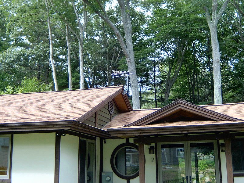 The installed antenna.
I purchased the EZ HD antenna, as well as the J-tube mounting bracket and balun from Denny's, then picked up a Holland
amplifier, some good quality splitters and a ground block from
Solid Signal ![]() ,
as well as a few other coax wiring goodies since I was also doing the voice & data wiring described above at the time.
I've had that antenna and bracket kickin' around for nearly a year, but now that I've been working on the gable end trim up
on the roof, I've finally gotten the antenna installed as well. For details of the installation, please look over the photos
in this section.
,
as well as a few other coax wiring goodies since I was also doing the voice & data wiring described above at the time.
I've had that antenna and bracket kickin' around for nearly a year, but now that I've been working on the gable end trim up
on the roof, I've finally gotten the antenna installed as well. For details of the installation, please look over the photos
in this section.
Once the antenna was up, I was pleasantly surprised by the number of stations the TV found when doing the channel scan... it came up 14 stations (I was hoping to get 5 or 6), and all but 2 of them are in High Def. The really big difference was in the FM reception, with crystal clear stations coming in at almost every stop on the dial. We're very pleased with the results (but if the Red Sox don't make the play-offs this year we won't get to try the picture-in-picture fun), and it all cost less than a single month's cable bill, so no complaints here.
Standby Power System
I'm not sure what the problem is with the utility power grid in these parts, but the reliability leaves much to be desired. No exaggeration - the power goes out or varies wildly on an almost weekly basis here. Most folks probably don't notice it, but I've got 6 uninterruptible power supplies (UPS) in the house for all the computers and home entertainment gear so when the wind blows or it rains, all the UPS's start beeping due to the variation in line voltage or frequency. I've lost hard drives and even fried a home theater receiver once due to the surges and outages, which is why I've got all those line-conditioning UPS's in the first place. We also get the occasional violent thunderstorm or hurricane from time to time (we're only a couple miles from the Atlantic ocean, after all), so having the UPS's for all our sensitive electronics makes sense.
Deciding on the Need for Standby Power: Spring 2008
Even though the power goes out briefly and we get strange surges during storms, it's not that often that we actually lose
power for more than a few hours. When I was doing all the planning for the new service panel and the subsequent installation,
it never occurred to me to add a proper home standby power generator. Then in the early Spring of 2008 (I think), we had a
freak late Winter ice storm and the power went out for 4 days. That was pretty miserable. 2 days in, the neighbor let me
borrow his generator and run it through a tank of gas just to make sure the freezer stayed frozen and to cycle the boiler
a few times. We decided then that we needed to get our own generator and never go through that mess again. I did lots of
online research regarding standby power systems, since the only generators I knew anything about were huge commercial
units from back in my days of data center planning. It became clear rather quickly that I should have taken
care of the standby power system while doing the new electrical service panel planning and installation. I guess
I was overwhelmed with holes in the roof and missing walls at the time, so the generator just never made it onto my radar.
 No space for a transfer switch here.
In order to have a standby generator automatically come on when the power goes out, there's lots of stuff that has to happen with the electrical panel and service entrance to get an automatic transfer switch in place. The transfer switch then detects when the power goes out for more than 10 seconds and fires up the generator (usually a large, natural gas fueled unit) to power whatever circuits have been hard-wired into the transfer switch. It also monitors the power lines and when power is returned, transfers the load back to utility power and shuts down the generator. Another option is to go for a manual transfer switch, which also needs to get installed within a couple feet of the main service panel. Like the automatic transfer switch, the manual switch has a limited number of circuits available which are hard wired into the main panel. When running on standby power those circuits are energized by a generator (usually a portable, gasoline fueled unit) that's simply plugged in to transfer switch with a large capacity extension cord. The down side of the manual switch is that it obviously doesn't automatically start and stop the generator as needed, but more importantly for us, it also needs to be installed right next to the existing service panel. The only location options we had for the transfer switch would have been to either put the thing in the living room on the other side of the wall near the service panel (for an automatic switch), or mount it outside the house next to meter box and service entrance (so we could plug in to a manual switch). Either way, I would have to remove a lot of the drywall around the main panel to get at the knock outs and install the wiring for the transfer switch circuits. This was not going to be a simple project.
Selecting a Generator: Spring 2011
Apart from the transfer switch issues, I also had to decide on a generator make and size. At least that part was easy
for me... There's lots of generator brands out there, but most of them use some sort of lawn mower engine and a generator
that's made who knows where. Lawn mower engines aren't made to run non-stop for a week, so I quickly eliminated most of what's
available. The choices left were pretty much from Honda Power Equipment or Generac. Hondas still have a standard little
gas engine in them, but as far as gas engines go, those are mighty fine units. Generac on the other hand, only makes one
thing: generators, and they've been doing that in Wisconsin since the mid-50's, doncha know. No lawn mowers or pressure
washers or whatever, just generators. I was pretty familiar with their big commercial and residential standby units,
but had already decided that we regrettably would not be able to install a residential standby unit due to the issues with
the service panel location. I was happy to learn that Generac recently started making smaller portable units. As far as
I'm concerned, when it comes to generators there's Generac, then there's everyone else. For more information about
these fine units, look over the Generac
![]() web site.
web site.
 The Generac GP8000E.
Sizing the generator was pretty simple too: get the largest capacity we could reasonably afford was the basic rule. All we really needed to run was the refrigerator and the heating system (1,200w for the 'fridge, and 800w for the heating pumps and H.R.V.), so a little 2kW generator might have done the job, but only barely. There's a lot to consider in addition to just what the proposed load might be - How would we be making the connections? What fuel will be used? How much stuff do we really need to power? What are the start-up loads compared to the running loads? How long will the generator run between fuelings? So, something bigger than 2kW would be needed to run any kind of load with a motor, since the power required for motor start-up can be as high as double the rated power draw when running... plugging in the 'fridge just to have it blow the breakers on some little generator every time it starts wouldn't help much. The unit would be connected with a plug and cord (more on that below), so I wanted to not get something too big otherwise the power cord would cost as much as the generator. Discarding the 2kW and smaller sizes put us basically into the 4kW and larger.
Looking at the prices of these units it became pretty clear we were going to be in the $1,000 neighborhood. A 6.5kW or 7kW unit would likely handle all the proposed loads and a few lights, but the price difference between a 6.5kW and an 8kW is only a couple hundred bucks. Once we get into the 10kW and larger, the price really changes (as in, the 10kW is double the cost of the 8kW). The other thing I liked about the 8kW size is it's rated for 10kW surge (to deal with those start-up loads) and it has a big 8 gallon fuel tank. It's rated to use about 1 gallon per hour, but that rating is based on running at half load. That's another reason to buy a larger generator than what you'll likely need - it's much less stressful on the engine (and more fuel efficient) to run an 8kW generator at half-load than to run a 4kW unit at full load. Also, at 8kW the 240v output is around 30a, so a 10AWG 4-wire extension cord will handle the load.
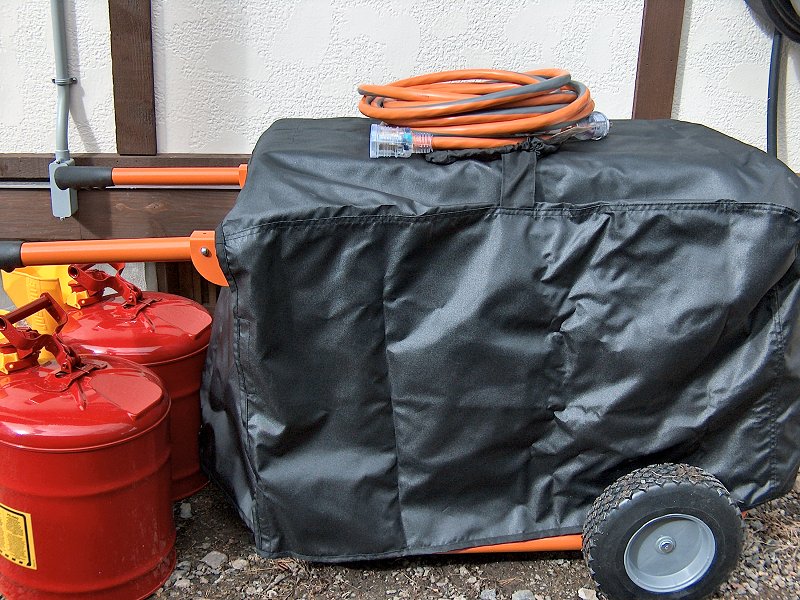 The generator extras.
Assuming we were getting a Generac 8kW unit still left a few variables. They make a couple different product lines
of generators in that size and again, the price varies between those by a few hundred bucks. Their portable generators
include the XG series, which are basically designed as a job site generator with all GFCI outlets, a nicely lit control panel,
and weatherproof covers on all the outlets. They also added a new XP "professional" series in 2011 which are even
more rugged than the XG series, including a more sturdy frame with a lifting eye, and a complete GFCI protected, weatherproof
control panel. Both nice, but not something we need for simple home standby power. The covered outlets would be nice of course,
but the GFCI system isn't needed at all, since all the house wiring already has GFCI breakers or plugs and the generator
loads are run through those circuits. All we need is the GP series, which doesn't have the GFCI stuff or any other
bells and whistles (although the new 2011 models now have covered outlets). Since we're not in California we don't need
the CARB compliant model (which saves about $250), however we did go for the electric start unit (which adds about $100),
since I wouldn't want to have to pull start the generator in the midst of an ice storm or hurricane. The unit we purchased
is the Generac GP8000E, model 5696-0. I had been planning to purchase a factory reconditioned unit from
CPO Generac
![]() , since I've purchased other
stuff from CPO and not had any trouble with them. However, they sold out of the electric start models by the time I'd made
the final decision (and Generac is replacing the old GP8000E with a new model that has the covered outlets now). I ended up
making the purchase through Electric
Generators Direct
, since I've purchased other
stuff from CPO and not had any trouble with them. However, they sold out of the electric start models by the time I'd made
the final decision (and Generac is replacing the old GP8000E with a new model that has the covered outlets now). I ended up
making the purchase through Electric
Generators Direct ![]() for
just under $1,200. The only thing that was a little odd was that I ordered a GP8000E model 5681, which is the 49-state electric
start model, but they shipped a GP8000E model 5696, which is the CSA compliant model. Not a big deal, since Generac
is changing the model line up, and I'm pretty sure EGD is just selling off whatever inventory is left. The 5696 is the same
as the 5681, it's just got a little different exhaust on it. They didn't charge me any extra for it, so no big deal.
for
just under $1,200. The only thing that was a little odd was that I ordered a GP8000E model 5681, which is the 49-state electric
start model, but they shipped a GP8000E model 5696, which is the CSA compliant model. Not a big deal, since Generac
is changing the model line up, and I'm pretty sure EGD is just selling off whatever inventory is left. The 5696 is the same
as the 5681, it's just got a little different exhaust on it. They didn't charge me any extra for it, so no big deal.
In addition to the generator purchase, we also picked up a few extras that of course added to the total cost. The generator doesn't do any good without a means to connect it to the house, so I bought a 25 foot, 30 amp, 4-wire generator cord. I was going to buy a 30 foot cord from Reliance Controls, but I noticed Home Depot had a nice orange and black cord with a covered end - since my generator was orange and black, I had to get that one instead. I also got a cover for the unit from Classic Accessories, which fits perfectly and has a couple spots in it for the handles to fit through. Lastly, we needed to get some proper fuel cans. Plastic gas cans are pretty awful, leaking fumes and expanding and contracting with any change in the weather. We decided to get the real deal with some proper Type 1 safety cans from Justrite. Eventually I'd like to convert this unit to natural gas, since it's going to get parked in a permanent spot after the garage is built, and Generac uses the same OHVI engine in their residential standby units (so getting the parts to make the switch should be possible). In the mean time I picked up 2, 5 gallon cans to get us by. If I don't make the switch to natural gas then I'll likely get another 2 or 3 cans, but at around $40 each, this should do for now. The cover and gas cans were all purchased through Amazon.com.
Connecting Standby Power
We still need a safe method of connecting the standby generator to the house wiring, and I just didn't like the idea of
putting a manual transfer switch with its breakers on the outside of the house. Some folks just use a bunch of extension cords
from the generator output panel to outdoor outlets, which back feeds power through those outlets and into the panel (or run
them through a window or door to plug in individual appliances). It works, but it's very unsafe. Not only is there a risk
of overloading the wiring in your house, but it's also quite illegal - if the house main breaker is left on when back feeding
the panel, you're essentially sending power back into the utility grid with your generator. While it's unlikely that the
generator would handle that load (trying to power every house between you and where ever the power outage occurred), the
fact remains that you're sending power into the utility lines and possibly energizing downed power lines. When a utility
crew attempts to re-connect those lines, they now have power in them thanks to your generator. Electrocuting the utility
workers is generally frowned upon if you want them to restore power to your house. Extension cords to individual appliances
work fine and are fairly safe, but that means moving appliances and running cords all over the place, and doesn't do anything
for loads that are hard-wired (like the boiler).
 Getting power to the panel (2 photos).
Fortunately there's another option for standby power supply into the panel, which is called a safety interlock kit.
All standby power transfer switches have some manner of safety interlock built into them, which prevents the possibility
of back-feeding the grid by making it impossible to have the utility lines connected to the standby power lines at any time.
A safety interlock kit does the same thing, but it's just a simple mechanical lock out that's installed in the home's service
panel between the main breaker and another breaker that's connected to the standby power supply. The interlock uses a
sliding metal plate that must be moved in order to engage the main or standby breaker, making it impossible to have both
breakers in the on position at the same time. A safety interlock kit is especially attractive for retrofit applications, since
there is no additional re-wiring of the panel circuits required - when running on standby power, you simply turn on the
circuit breakers for whatever you want to supply power to, and leave the rest of the panel off. The safety interlock kit
does require the addition of a 2-pole, 240v 30a breaker (depending on the size of your generator) for standby power input
located right next to the main breaker, which might be a problem if you have a packed service panel. We still had plenty
of room near the main breaker so installation space wasn't an issue. Safety interlock kits are also relatively inexpensive
(less than $150) compared to a transfer switch (which is at least $250). Since we have a Murray electrical panel (made by
Siemans), I selected a Siemens Safety Interlock Kit #ECSBPK03, purchased from
Kirby Risk
![]() . More information
regarding Siemens / Murray interlock kits is available in their Power
Interlocks Brochure
. More information
regarding Siemens / Murray interlock kits is available in their Power
Interlocks Brochure ![]() .
.
With an interlock kit selected, I still needed to get power from the generator to the panel. I had already added a new 10/4 line to the panel when installing the central air conditioner, and wasn't looking forward to trying to snake another one of those big cables through the already crowded wall space below the panel. Instead I decided to just run the line outside the house using the meter box on the other side of the wall from the service panel. I had a knock-out available next to the main power input conduit, so added a bit of 3/4 inch conduit and an angle box to route the wire down the wall to the water table trim. I ran the entire 35 foot length of wire through that conduit and hole (leaving some extra up top for inside the service panel), then foam sealed the hole and caulked around the opening, adding a screw through the angle box into the wood to secure the box in place. Back under the house once more, I routed the wire up above the radiant insulation and along the floor joists over to the East wall, where I was planning to install the power inlet box for the generator. The idea is that when there's a garage there, I'll be able to park the generator either behind the garage or inside (with a door open), and still be well within range of the plug with the 25 foot generator cord. I mounted the Reliance Controls PB30 power inlet box on the side of the house, under the roofed section that will eventually connect the house to the garage. All the was left to do now was some work in the service panel.
 The interlock kit in the panel (3 photos).
Interlock Kit Installation & Service Panel Labelling
Interlock kit installation began with moving a couple of existing breakers in the panel to make room for the new standby
power input breaker. Not only must the standby input breaker be up and to the right of the main breaker (since my panel
is installed upside down, that is), the breaker spot next to it must also be vacated since those lugs in the panel would share
power with the input breaker. The interlock kit makes it impossible to install a breaker there too, so there's no chance
of screwing it up. I had enough slack wire inside the service panel so re-locating the Clothes Dryer, Well Pump and
Central A/C breakers was simple enough. I then wired in and mounted the new 30a breaker for the standby input. The interlock
kit doesn't require any modification of the panel (some after market models do), but it does take a little wiggling and pushing
to get into the right spot. It has a set of clips that snap into place around the input breaker, then mounts with a screw to
the main breaker. Because off how the interlock bars work, I found it easiest to sort of hang the interlock on the panel face,
then attach the panel face back on to the enclosure ensuring the clips engage the input breaker. With the interlock installed,
I then spent a little time re-labelling the service panel to clearly mark the standby power input breaker, as well as indicate
which breakers should be engaged when running on standby power.
The day after I finished installing the interlock, I decided to fill the generator with oil and fire it up (I'd had it plugged in to charge the battery but hadn't started it since I received it). The wind was blowing pretty well, and just as I finished topping up the engine oil, the power went out. I put in a couple gallons of gas and hit the start button, and the generator fired right up. It wasn't as loud as the lawn mower (but it's still pretty loud), so I left it in the temp garage with the door open to help dampen the noise in the house. I ran the cord from the generator over to the plug, then came inside and switched off the main to engage the standby input breaker. Oops - I forgot to turn off all the stuff in the panel first! All the lights and TV came back on, and I heard the 'fridge restart as well as the pumps on the boiler fire up. I could tell by the sound of the generator that it had quite a load on it, but it didn't shut down or blow any breakers. I guess 8kW is enough output to run the whole house. We went through the panel (I hadn't labelled anything yet) and switched off a lot of the breakers while keeping enough engaged for a few lights, outlets, and the essentials. The standby power system had passed it's first unplanned test with flying colors. The only thing we noticed was that there's no way to tell when the power came back on now. The folks across the street have a big Kohler residential generator, so seeing if their lights are on doesn't work. Looks like we're going to need to get one of those Reliance Controls PowerBACK™ sensors to call this project finished.
 The PowerBACK™ monitor.
I ordered the PowerBACK™ from Amazon.com and had it a few days later, ready for installation. The thing is very simple to install, although I wasn't sure where I was going to mount it. Luckily it has a magnetic back panel, so I could just stick it to the panel cover. Not pretty, but effective. I removed the panel cover (but left the section with the labels hanging on the breakers, since the interlock kit sort of holds it in place), and ran the 2 wires from the power monitor into the panel. I put a piece of woven cable protector over the wires (since they had to sneak out from under the edge of the panel cover), then connected the ground wire to the panel ground buss and wrapped the induction cable around one of the hot leads ahead of the main breaker. A couple wire ties secured the induction lead in place, and everything went back together. As I was re-installing the panel cover, the lights in the house flickered a couple times (it was another very windy day outside) then all the UPS's started beeping and the power went out again. I told you we lost power here all the time! The PowerBACK™ comes with a 9V battery, so I popped it in, turned the thing on, and went outside and fired up the generator. An hour or so later something that sounded like a smoke alarm started making noise, which meant the power was back on and the new unit had done the job. It's comforting to know we're fully prepared for future power outages.
The Lightening Strike
Big Bada-Boom: Summer 2019
It started as a typical mid-Summer thunderstorm, moving down the Merrimac Valley and out to the Atlantic. As it drew closer to the coast, it kept get
bigger on the radar, and much darker in the sky. We could see some flashes off to the West as it approached, followed by some really loud thunder.
As it got closer the winds really kicked up, and we could start to see the lightening bolts dancing around with thunder making those big cracks
that go with lightening strikes. Yep, time to stop standing on the porch to watch the lightening and get inside — then it happened…
first there was a really bright flash, followed immediately by a huge craaack that was right on top of us and
made the whole place shake. That one definitely hit something near by…
 The blown-apart sprinkler timer (4 photos).
The power didn't go out and the place wasn't on fire, so it hadn't hit the actual house or any utility poles in the vicinity (and there are lots of tall Oaks, Beeches, and White Pines near by that should take the hit before the power lines do). As the storm quickly moved on to the East, we looked around a bit at the woods behind the back yard and didn't see any trees that were split open or burning. It had certainly hit something close, but we never were able to figure out what it might have been. Then we started to see the damage it had caused in the house and garden.
The first thing we found was that there was a small "crater" on the hill right next to the big Red Oak between the deck and the karensansui . The new hole was about 6-inches deep and about a foot in diameter, with the control cable for some of the irrigation valves parted in the center, and mangled up out of the crater with all the wires burnt to a crisp. Perhaps it had hit that big Oak (which has since been removed after a limb fell on the house — Oh, maybe it did get hit and that caused the limb to come down a year later)? We went up into the tea house to see if the other sprinkler valves would still work, and that's when we found the big mess: The sprinkler control valve that had been mounted just inside the door behind a little sliding panel had literally blown apart. All that was left where it had been mounted was the back of the case, with a bunch of burn marks in it. The rest of the controller, along with the sliding door cover and all its trim, had been blown off the wall and scattered around the tea house in pieces.
Okay, so I guess we're gonna need a new sprinkler system controller. Over the next few days we also found lots of other stuff had been damaged due to the strike. As I said above, the power never went out, and the GFCI breaker that provides power for the tea house hadn't tripped. But somehow the surge from the strike had made it into the house wiring, and it turns out it cooked many of the little plug-in "wall wart" transformers in the place. All the networking components were off and needed new transformers (but the USB hub power and cordless phone power were fine, even though they're in the same power strip) The transformer for the outdoor low-voltage lighting around the deck was no longer working, and even the little 16VAC transformer for the door bell had cooked. The worst of it was that the old Sony home theater receiver went into "protector" mode when we tried to power that up, so that was toast as well. I also found out in the Summer of 2021 that the 1960's deep well pump was no longer working, even though it had run year after year without any trouble. I suspect that may have also been damaged in the strike, since the pressure switch still worked, but no joy with the pump itself.
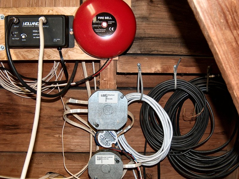 The new doorbell stuff (2 photos).
I scrounged up some old power supplies to get the networking up again, then ordered a new sprinkler controller and low-voltage lighting transformer. Once I received the new controller and got it installed (and repaired the cable bundle), we found that one of the valve solenoids had also cooked and would need to be replaced. Santa got us a new Sony home theater receiver for Christmas that year, so all that was left was to get the doorbell working again. I had never been happy with the pitiful little doorbell unit I'd installed years ago — and it was an actual bell, not some "ding-dong" chime thing. I figured this would be a good opportunity to get a bell that we could actually hear. After a bit of diggin' around on the 'net, I decided on the Safegaurd Supply 6-inch Fire Alarm Bell. This thing is nice and loud, and sounds like a proper bell. The problem is that the bell requires 12VDC to operate, not 16VAC like standard doorbells. AC powered doorbell buttons are usually wired with two wires: a "hot" wire from the transformer runs to one side of the doorbell button, then the other side of the button is connected to the bell or chime activation solenoid or relay. The other side of the solenoid or relay is then run back to the "neutral" side of the transformer (so current is always flowing through the circuit). The bell doesn't constantly "ring" because the bulb in the doorbell button is using enough current to prevent the relay or solenoid from closing. When the doorbell button is pushed, the contacts within the button close so the current takes the "path of least resistance" through the closed contacts, and the relay or solenoid activates (and which is why the light goes out when the doorbell is pushed). All this means a standard illuminated doorbell button won't work with DC power. With DC the bulb lights up fine, but it doesn't use enough current to prevent the chime or ringer from running constantly. An illuminated doorbell button designed for DC power would need a third wire as a dedicated ground wire for the bulb, and I don't think such a thing exists (and even if it does, I certainly wasn't going to run a new 3-wire bundle from the attic to the front door).
The solution to all this doorbell stuff was to replace the cooked 16VAC transformer with a little 12VDC, 15-watt transformer. I found a tiny
thing on Amazon for $15, and it's even waterproof and rated up to 140°F, so it'll be fine in the attic. Then we needed to figure out
a proper replacement for the standard illuminated push button doorbell. If you've six or eight hours to waste some day, do a web search for
doorbell buttons. Yeesh. After lots of browsing, we finally decided on a button from House
of Antique Hardware![]() that looks pretty good
(I like the ones that say "Press" too, but they're all to large to fit on our narrow door trim). I got the new 12VDC transformer,
big bell, and the new doorbell button installed in the Fall of 2020, and that finally took care of everything that had been damaged by our
lightening strike. Now I'm investigating adding a whole-house surge suppressor, as replacing one of those with every big lightening storm would
be a lot easier and less expensive than finding and replacing all the various damaged electronics we had just been through.
that looks pretty good
(I like the ones that say "Press" too, but they're all to large to fit on our narrow door trim). I got the new 12VDC transformer,
big bell, and the new doorbell button installed in the Fall of 2020, and that finally took care of everything that had been damaged by our
lightening strike. Now I'm investigating adding a whole-house surge suppressor, as replacing one of those with every big lightening storm would
be a lot easier and less expensive than finding and replacing all the various damaged electronics we had just been through.
↑
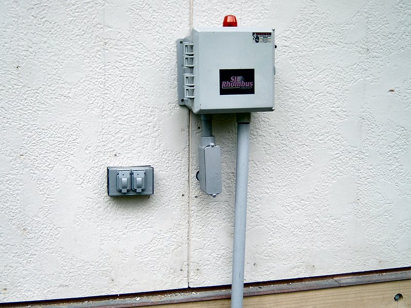
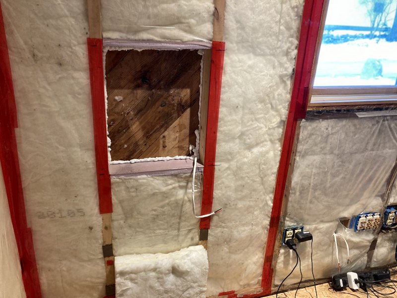
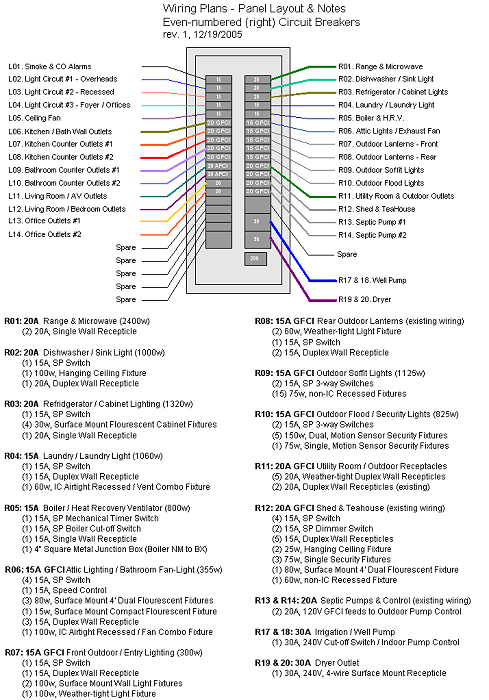
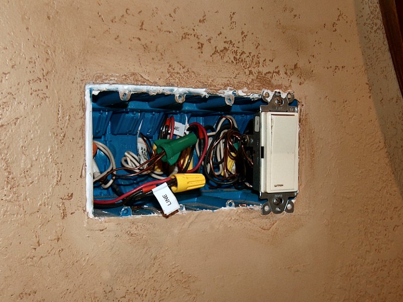
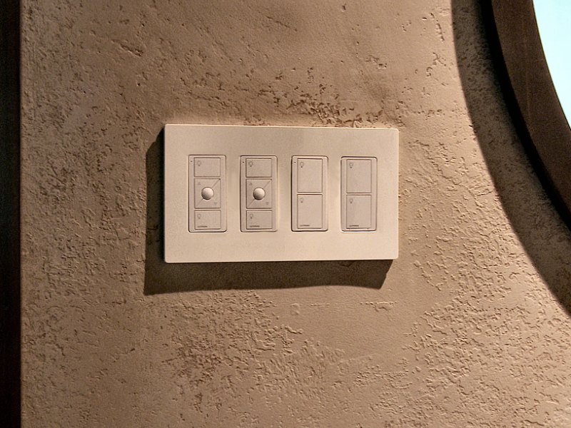
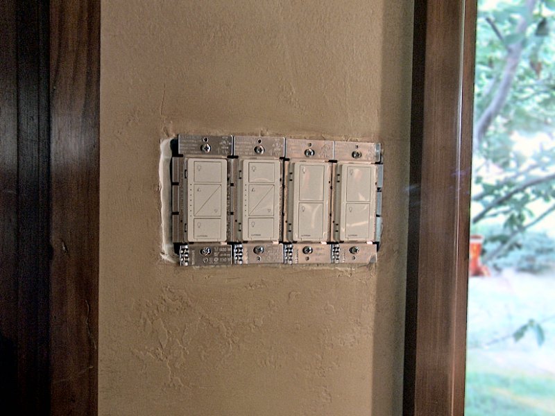
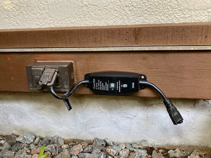
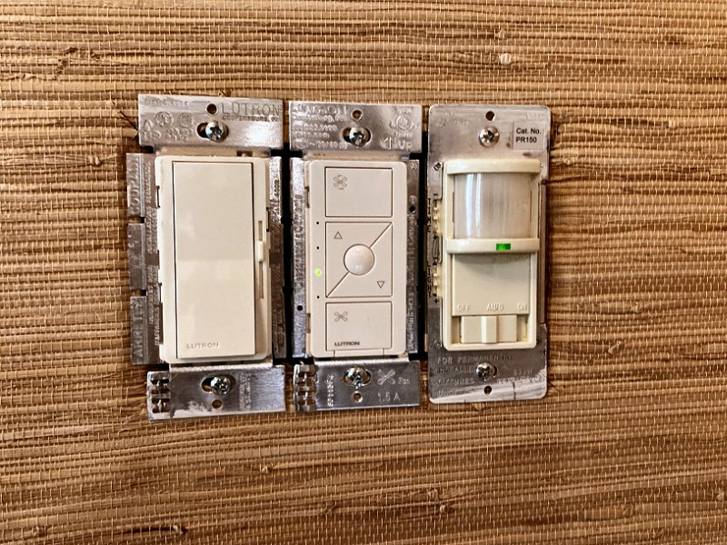
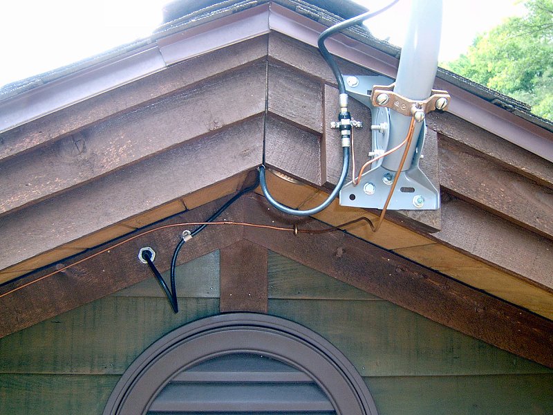
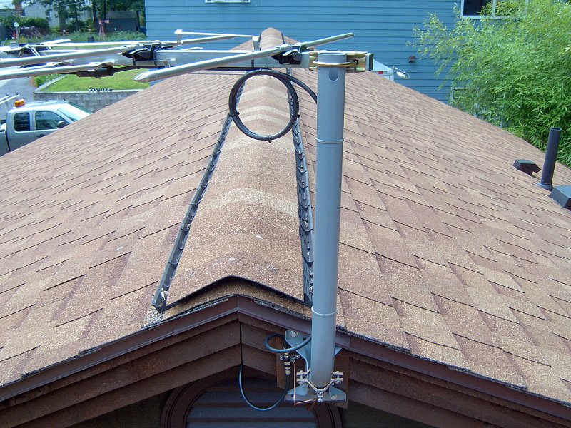
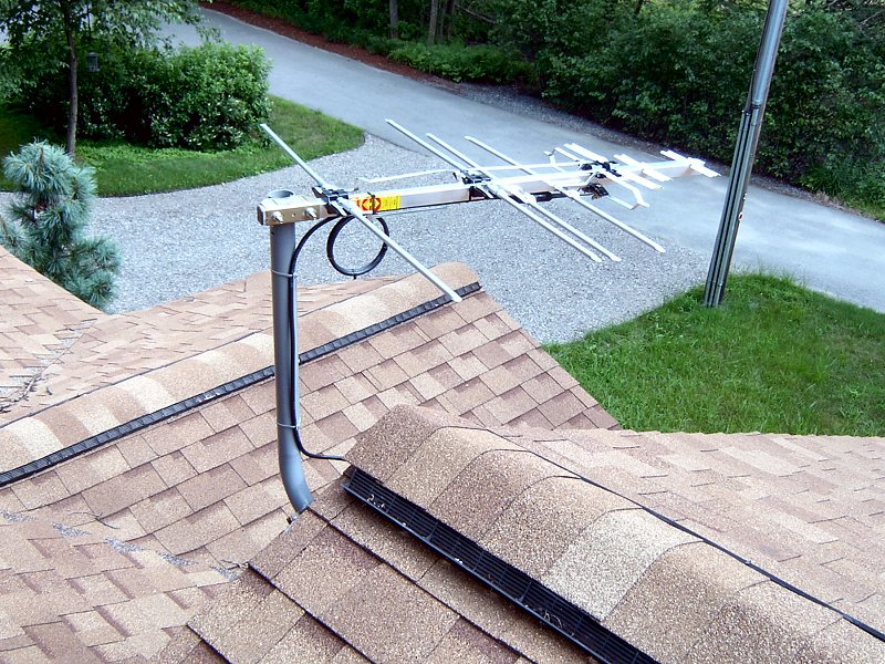
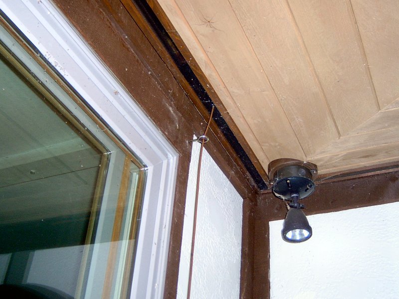
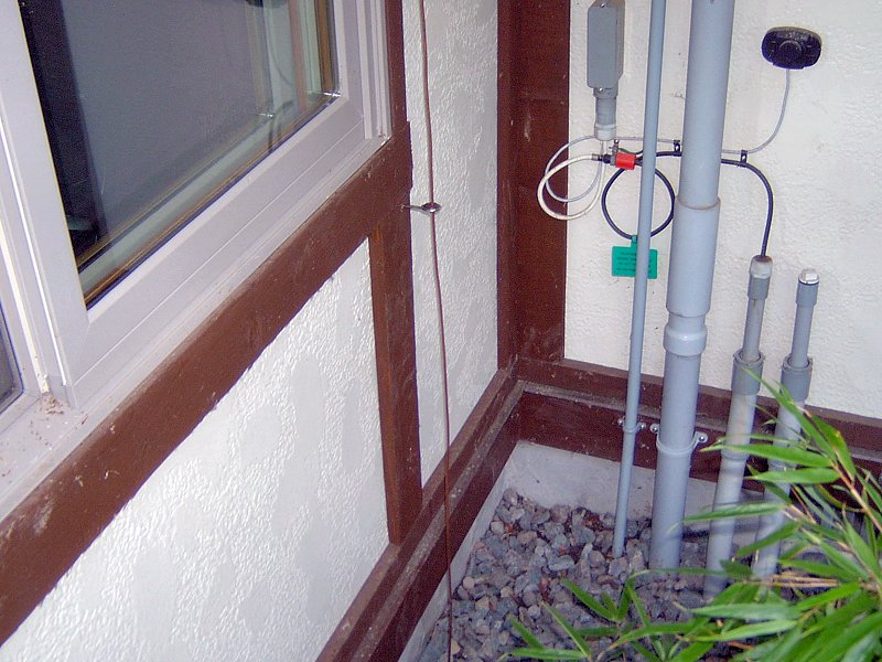
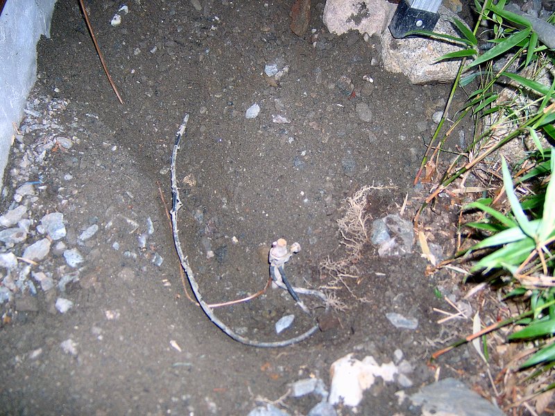
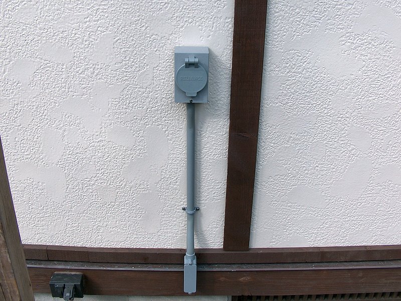
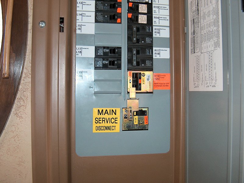
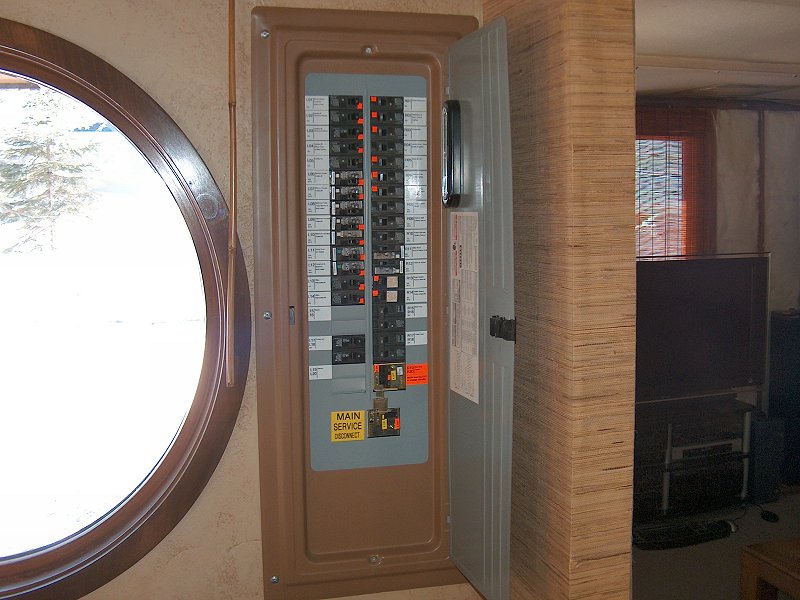
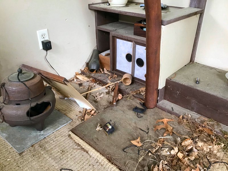
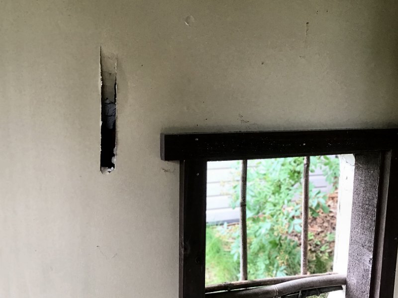
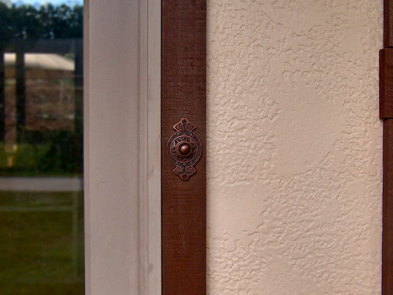