

Updating the Heating, Ventilation and Air Conditioning Systems
 The new boiler.
Like the wiring and plumbing, the HVAC systems we're a total wreck when we purchased the house. As described in the Mechanical introduction, our heating system for the entire house was a counter-flow, direct-vent, wall mounted furnace. It was really loud, and didn't do a lot for making the place toasty warm. We much preferred the woodstove, which was a little Jotul 602 that I'd fitted into the fireplace many years ago. I no longer had the time or inclination to play with firewood, so we didn't mind so much that the woodstove went away with the chimney when the house renovation began. The old Jotul is still going strong - I gave it to a neighbor up the street who fitted into his fireplace, and loves it. With the removal of the Jotul, we basically had no heating system in the Fall of 2005 when we knocked down the chimney and the weather was getting colder. It was going to be a chilly Winter. As for the ventilation and air conditioning systems, that's easy - there weren't any. At least nothing like a whole-house fan, or central A/C. We had a little window A/C unit that we'd mostly run on the fan setting throughout the Summers, except for those couple brutal weeks in August when we get our 90° days with 90% humidity. I was planning to change all that with the renovation.
The first order of business was to get some manner of heating system online for the Winter of 2005. We still had our old floor furnace installed, although it hadn't worked in at least 10 years - ever since it had been flooded and deemed un-repairable by our old propane gas supplier. I figured it was worth a shot trying to repair it, since my options were pretty limited at that time. I had been under the house and disconnected the vent from the chimney before we took the chimney down, and the gas line to the unit had been snipped off when the landlord installed the wall furnace years before. Pulling the unit out of the floor wasn't too difficult, and I was able identify it as an Empire Comfort Systems® 32,500 Btu floor furnace, model 3588. I was surprised to find the company still existed, and even more surprised to find they still made the same furnace (if it ain't broke, don't fix it, I guess). After a few minutes on the phone with their parts department, I had a new gas valve and pilot assembly on the way, as well as a proper thermostat. I cleaned up the old burner with a wire brush, installed the new parts, and grabbed a few chunks of gas vent pipe to rig up a temporary chimney through the crawl space access door. The old monster fired up on the first try, and we had heat again. I really liked our old floor furnace — it didn't need any electricity, and while not very efficient, it did make the house comfortable.
Radiant Floor Heat
Sometime in the early 90's I did a brief stint working for a homebuilder / architect on a big house he was building on Cape Cod. It was sort of in the middle of nowhere down there, so the deal was the work crew "camped out" in the house for the week, and would return home on the weekends. I think I stayed for a week, then went back to work in his millwork shop instead. Anyway, the point is it was Winter, and the house had just had windows and doors installed and the heating system turned on. It was my first experience with radiant floor heat, and I was sold. I'd never been impressed with the whole idea of blowing warm air around a house all Winter to try and heat it, since by default there's always a "draft". Baseboard heat, whether electric or hydronic, sounded okay, but there needs to be some thought about room configuration and blocking heaters, etc. - we were taking walls out, and not going to have a lot of places to put baseboard heaters. I'd heard about hydronic radiant floor heat, but mostly in the case of tubing installed in poured concrete floors in commercial or industrial buildings, and had no experience with it in a residential setting. Spending a week sleeping on the stuff sure changed my mind. I was already familiar with the concept of radiant heat after having lived with a woodstove for many years - the heat source radiates to other objects in the space and heats them up, then those objects warm the air around them to make the entire room warm. It's a much different type of warmth than a forced-air system, which warms the air in the room directly by forcing heated air into the space while cooler air is drawn into the furnace and heated again. And there's nothing good anyone can say about a forced air system to try and convince me it's better than waking up and stepping onto a warm floor in the middle of Winter.
Planning the New Heating System: Fall 2005
We decided to use hydronic radiant floor heating as our heating system, but there were still many details to be addressed before any
type of installation could begin, like figuring out the heat source and fuel type. Selecting the heat source and fuel type was very
simple for us - while we'd been working on the landscaping and septic system, Keyspan Energy came through the neighborhood with an
offer we couldn't refuse. We'd been running that horrid wall furnace on Liquified Propane, and I hated it - not that LP gas is a bad thing
all by itself, but our LP gas supplier was just awful. We ran out of gas a couple times a year, even though they were supposed to
keep the tank full. I'd never had such poor service from a company that was supposed to be in the service business. I had no interest
in keeping a LP tank in the yard, and even less interest in installing a new tank for fuel oil then having to deal with another company to try
and keep that full. Keyspan was considering bringing Natural Gas to our neighborhood, and was knocking on doors to see what kind of
interest there was in signing-up for it. They were going to install it to the house and hang the meter at no charge, and offered a free
furnace or hot water heater as in incentive. They had perfect timing. We had the new NG line installed in the Summer of 2005, then
took delivery of a new Burnham Revolution® RV4 96,000 Btu gas-fired boiler. Since I knew we were going to be
re-building the utility room to house the boiler, Keyspan didn't get picky about having it installed, and basically just dropped the
thing off in the crate (the neighbor the plumber assured them he'd be installing it soon, which helped). Now I just had to figure out
where I was going to put it, along with the design for the rest of the heating system.
 The heat tubing layouts (4 sheets).
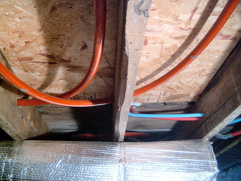
There's pretty much two methods of getting hydronic radiant floor heat into a house: install 1/2-inch cross-linked polyethylene (PEX) in grooves in the sub-floor from above before installing the finish flooring, or install PEX under the sub-floor through holes drilled in the floor joists, then attach it to the bottom of the flooring. Using the grooved sub-flooring / install from above option is by far the easiest method for new construction, but no so much when dealing with a retrofit installation. My ceilings were already pretty low (around 7-foot, 4-inches) so I didn't want to keep shrinking the room by adding a new 3/4-inch think sub-floor, then another 1/2-inch of finished floor on top of that. We were planning on using a laminated "floating floor" for most of the house, so I wasn't planning on removing the existing floor either. It looked like the best option for us would be the standard retro-fit approach of drilling holes in the joists, then attaching the PEX to the subfloor from below with metal heat-dissipation plates. It would be a lot of work, but far less expensive than using the pre-channeled sub-floor panels inside. If I had it to do over again...
The next step was to determine how much tubing I was going to need, and how we were going to route the heat flow in the tubing. The boiler output can be split up both as zones and loops - zones are separate sections of the house that are controlled by their own thermostat (which controls a pump at the boiler for that zone as well), and loops are smaller sections of tubing that deliver the heat within each zone. A loop can only be so long before the heated liquid within the loop no longer transfers any heat to the space, and if it's too long, the liquid will cool so much that it becomes very inefficient to re-heat the returning liquid at the boiler. It's also important to try and keep all the loops about the same length (within a few feet of each other), so that they all heat up about the same, and all return about the same temperature liquid to the boiler. With our house at just under 1,000 square feet, we went with just one zone / one thermostat, but to keep the loops a reasonable length we designed for three loops. It was no small feat figuring out how to pull off three equal length runs of tubing in our odd-shaped footprint, but after a few attempts, I came up with a plan for all the tubing runs. Each loop is about 225-feet long, and the plans show the return end in blue since that's where the cooler liquid is returning to the boiler and not doing much heating. For the living room and bedroom loops, the heat tubes were insulated with pipe insulation between the boiler and the start of their run in the joist bays, as well as where ever the tubing ran under an appliance or cabinet, since there's no reason to heat those areas. I also insulated the tubing in the area directly around the toilet flange, since there's enough heat in the tubes to melt the wax ring that seals the toilet to the flange. In areas that will be tiled, I doubled the tubing runs in each joist bay to provide some extra heat output - nice in the bathroom and kitchen for toasty toes, and useful in the genkan to dry up snow or water that might get tracked into the house. The outermost joist bay doesn't have any heat tubing in it since it's bounded by the outer rim joist and would suck up a lot of heat to try and warm (and no one stands right up against the wall anyway), but it's still completely air-sealed and insulated.
Installing & Insulating Radiant Heat Tubing: Spring 2006-Fall 2009
That's right... 3 years to get it all installed. I did a good deal of research online to determine what kind of tubing to
use for our heating system, and while it seemed 1/2-inch PEX was the most common for new work, I was intrigued by the larger 7/8-inch
thin-walled PEX I'd found on a few supplier's sites. The thin-walled tubing supposedly put out over 70% more heat than the smaller
thick-walled stuff, so it was possible to provide good heat with just a single tube in each joist bay, as opposed to double-tubing each bay
with the 1/2-inch stuff. For extra heat, the 7/8" could also be double run inside a bay if needed as well. I decided to use the thin-wall,
and also decided to use the "heat-plate' attachment method. Other attachment methods use large staples or clips, but I like the idea of
using a metal plate to hold the tube to the bottom of the floor, and that it helps draw heat out of the tube and in to the floor. I
purchased all my supplies from the Radiant Floor Company
![]() up in Vermont, and was ready to
get started.
up in Vermont, and was ready to
get started.
 Radiant heat tubing in the bathroom.
Drilling the Joists
While waiting for the first roll of tubing to arrive, I went under the house and started boring holes. I borrowed the plumbers Milwaukee
1/2-inch Hole-Hawg®
![]() drill, which is a beast of a machine but will drill through anything with the proper bit. He didn't use it much
since it was so heavy, so said he didn't care if I kept it for months. I purchased my own Milwaukee 1-1/4-inch self-feed bit and extensions
for it, which worked great since the bit sort of pulls itself through the wood, rather than needing a lot of pressure behind it to go.
Lying on my back and maneuvering the Hole-Hawg® into position was pretty awkward, and if the joists were too close together to get the drill
into place, I'd have to chuck in a few extensions to reach the right spot through the holes from the next bay over. I managed to get
all the holes in the right spots to start on the old porch area over the course of a couple days, then the misery began - threading tubing.
drill, which is a beast of a machine but will drill through anything with the proper bit. He didn't use it much
since it was so heavy, so said he didn't care if I kept it for months. I purchased my own Milwaukee 1-1/4-inch self-feed bit and extensions
for it, which worked great since the bit sort of pulls itself through the wood, rather than needing a lot of pressure behind it to go.
Lying on my back and maneuvering the Hole-Hawg® into position was pretty awkward, and if the joists were too close together to get the drill
into place, I'd have to chuck in a few extensions to reach the right spot through the holes from the next bay over. I managed to get
all the holes in the right spots to start on the old porch area over the course of a couple days, then the misery began - threading tubing.
Threading the First PEX Loop
The first loop I tackled was the run for the genkan and office area, since the carpentry for that area had
been completed first to build the utility room. By the time I'd finished working on the carpentry and some of the plumbing and electrical
work to allow the boiler to get installed it was mid-February, and not exactly warm outside. Still, we needed to get the heat going so I
popped the ties on the 250-foot bundle of tubing and crawled under the house with one end. What a horror show that was. As long as the
tubing was going with a curve in the same direction as it had come off the coil, everything was fine. As soon as I needed to make a
bend in the opposite direction though, that frozen tubing would have none of it and would just kink and not budge. Kinks in PEX aren't
really a problem, since the kink can just be warmed a bit with a heat gun and it pops right out without harming the integrity of the
tubing. However it's very inconvenient to have to stop and remove a kink every five minutes as you try and thread tubing through joist
bays. As I recall, I think I made it through three bays on the first day of wrestling with the stuff. Not good.
The procedure I eventually worked out was to uncoil ten or fifteen feet of the stuff outside, then crawl under and pull all that slack through the first hole and let it sort of flap around loose in the joist bay and on the ground. Next I'd shimmy down to the other end of the joist bay to the next hole, and work all the slack through that hole and into the next joist bay. Whenever I needed to make a turn in the tubing to get from one bay to the next, I had to give it a twist as I fed it through the hole, so it would turn the right way and not just kink every foot as it tried to make the turn. It was clear that this was definitely a two-person job - one person at one end of a joist bay to pull the tubing and feed slack into the bay, while the other person at the other end twisted and fed the slack through the next hole. I didn't have another person available, since the lovely bride was working and no one else I knew was foolish enough to want to go under the house in February and fight with frozen tubing. Somehow I got that first loop finished, but it took a really long time. After crawling around on frozen gravel for a couple weeks I had had enough.
 Making a heat plate.
Heat Plates for the Genkan Floor
The boiler had been installed and fired up to run the indirect hot water heater, so once I had the first loop of tubing threaded and connected
to the boiler, the plumber came back to get the heat portion running. He pumped in some anti-freeze, then bled and pressure tested that
first loop in short order and we had some heat circulating at last. It wasn't actually making the house warm yet though, since I hadn't
attached any of the tubing to the floor and hadn't insulated yet. Reluctantly, I crawled back under the house with my home-made jig to
form the heat plates, a bunch of malleable aluminum sheets, and the staple gun. I banged out my first plate and stapled it up. It looked
pretty good, so I started on the second one and as I was stapling that up, the first one fell off. Hmm. The manual staple gun with little
1/4-inch long T-50 staples wasn't gonna make it. Off to Home Depot I went to get an electric stapler and bigger staples. I'd already
wasted most of the day, so I just grabbed any old gun and a box of 1/2-inch long T-50's and headed home to see if I could make some progress
with that. Nope - wrong stapler. I picked up some light-duty thing that used T-20 or T-25 staples. Useless. Back to the store to return
that, and spend the big bucks on the big yellow Arrow electric gun. This would work just fine! Back under the house... bam bam bam
jam bam jam bam bam jam jam jam. There was much cursing and throwing about of staples as I tried to un-jam the thing pretty much
every other squeeze, until after an hour of this it stopped firing all together - something was borked with the trigger. I was not happy,
and stopped for the night after having installed only about half a dozen heat plates.
This project wasn't working out too well - threading the tubing had been just miserable work, and now I couldn't manage to get the heat plates attached without a fight. The cost of using 1/2-inch PEX and pre-grooved floor panels was looking more reasonable all the time, but it was too late to turn back at that point (and I had another 500-feet of tubing waiting to be installed). I eventually got the electric staple gun working well enough to finish the first loop (the piston needed some lubricant, apparently), but it was still jamming pretty regularly and was generally troublesome. Before I attempted to install the remaining two loops under the main house, I was going to have to find a better attachment method, and also wait for warmer weather so the tubing would be easier to work with. The good news was the floor in the entry way and offices was actually kind of warm, even though I still needed to insulate underneath it. As I recall, I stopped working in the heat stuff around March of 2006, and turned my attention to the roof and electrical work at that point.
Insulating the Genkan Floor
Insulating an under-floor radiant heat system isn't the same as insulating say, an attic - fiberglass insulation is made to reduce conductive
and convective heat flow by slowing the heat transfer from warm air to cool air because it traps layers of air in between all those little
strands of fiberglass. It really doesn't do anything to slow radiant heat flow at all. If I put fiberglass batts under the
radiant heat tubes, they'd just slowly warm up the fiberglass as it absorbed their radiant heat, then pass that heat to the surrounding
cooler air below the house. In order to "control" the heat output of a radiant heating system, we need to reflect the radiant energy toward
the thing we want to heat up (the floor). It'd also be nice to isolate the air around the heat source to limit air movement, which will
reduce convective heat loss around the pipe and heat plates. Remember, the point is to radiate heat into the floor, then let the floor warm
the objects in the house by conduction and warm the air in the house through convection. So, the right stuff for the job would need to be
reflective, and also have some way to separate the warm side from the cold side to minimize conductive loss. Hooray for bubble wrap!
Bubble wrap!? Yep, that's essentially what radiant floor insulation is. It's a little fancier than the stuff you pack dishes in though...
It's called Double Reflective Insulation, and consists of two layers of foil faced bubble wrap that are bonded together. The foil face
reflects 96% of the radiant heat back up toward the floor, and the bubble layers provide a little dead air space to stop conductive losses.
Double reflective insulation "off the roll" only as an R value of 3.6 (because of the little bubbles), but when it's installed and
air-sealed along the bottom of a 2 x 8 floor assembly to form a vapor / moisture barrier, it provides an effective R-value of 16.8 because
of the big "dead air" space. I used
Reflectix®
![]() double-bubble, although there are many
manufacturers that all make basically the same thing. I purchased a few 4-foot wide and 16-inch wide rolls to get started, and since it was going
to require a staple gun for installation, I also picked up a Porter-Cable fine-wire upholstery stapler. I'd had rotten luck with manual and
electric guns, so perhaps the pneumatic stapler would work a little better.
double-bubble, although there are many
manufacturers that all make basically the same thing. I purchased a few 4-foot wide and 16-inch wide rolls to get started, and since it was going
to require a staple gun for installation, I also picked up a Porter-Cable fine-wire upholstery stapler. I'd had rotten luck with manual and
electric guns, so perhaps the pneumatic stapler would work a little better.
 Insulation tools (2 photos).
Ah, what a difference the right tool makes! That little stapler is a joy to use. It's never jammed, and I'm more than half way through my second box of 10,000 staples. There's no safety trigger on it, so it's easy to get into tight corners and still fire a staple, and the long nose reaches over and around stuff I'd never be able to get at with the other guns. There's no depth adjustment (thus less stuff to get in the way of the tip), but the depth can be set by adjusting the pressure at the compressor. I added a 16-inch long, swivel-ended "whip" to it as well, so the bulky air fitting doesn't get in the way of getting the thing up into joist bays.
Now that I had a proper stapler, the insulation installation was a breeze. I started with the 16-inch wide rolls working around the perimeter of the space, which I ran up the rim joist with a couple inches folded on to the floor. I then stapled it to the sill, and folded the remainder toward the center of the space, attaching it to the bottom of the floor joists. Next I applied the 4-foot wide rolls to the bottom of the joists by lying on my back at one end of the space, then pretty much sat the roll of insulation on my chest and unrolled it over the top of myself, then gave it a kick with my feet. Next I'd staple it up to the bottoms of the floor joists, kicking the roll as I scooched along under the floor. Once I reached the end of the section I was working, I'd cut the roll, turn around and do the same thing going in the opposite direction. The rim joist work was a bit fussy, but doing the big rolls went very quickly, and I finished getting it all stapled up in an afternoon.
Sealing the Insulation
The last task to complete the insulation is to air seal the Reflectix® in order to form a moisture/vapor
barrier between the heated joist bays and the rest of the crawl space. To seal seams in the double-bubble I simply used a good quality
aluminum tape. The stuff is super-sticky and seems to be holding up very well on the few sections I've inspected on later "visits" to
the crawl space. Any electrical or plumbing penetrations were sealed with gun-dispensed "Pur-fill" foam. The nice thing about the foam
gun is that I can leave a can screwed on to the gun for months, and when I need to seal something I just open the valve and it still
works fine... try that with a can of Great Stuff™. The foam gun kit was fairly expensive, but considering the money I saved by not
having to throw away a half-a-can of Great Stuff™ every time I finished sealing something, I think it was worth it. Another nice thing
about the foam gun is I can adjust the output down to a very fine bead, which is all I needed when sealing the perimeter of the double-bubble
to the sill. I got the foam gun kit and sealing tape from
Energy Federation Incorporated ![]() ,
which offers all their energy savings products at a discount, depending whether or not your state's utility companies participate in their
partnership. Keyspan / National Grid is part of the EFI discount program, so I get a nice 20% discount on everything I buy from them.
EFI's also located in Massachusetts, so I receive most things I order within a day or two or ordering them.
,
which offers all their energy savings products at a discount, depending whether or not your state's utility companies participate in their
partnership. Keyspan / National Grid is part of the EFI discount program, so I get a nice 20% discount on everything I buy from them.
EFI's also located in Massachusetts, so I receive most things I order within a day or two or ordering them.
One issue I had with the gun is that it needs to be held upside-down (can on top) to function properly - works great when sealing stuff in walls or the attic, but not so much when used in the crawl space. At first I was just tipping the gun to the side while trying to keep the can at the proper angle to still dispense foam, and not just blow all the propellant out of the can instead. That worked okay, but I could only get about a third of the can used before I had to screw on a fresh can (I used non-empty canisters for foam sealing elsewhere inside the house). I noticed the gun comes with a little barbed-tip nozzle, so I ordered a 25-foot length of "fuel and lubricant" yellow PVC tubing and some tiny little clamps for it from McMaster-Carr to use as a flex nozzle. When I need to apply foam in a location that's above the gun now, I add a foot or so of the yellow tube to the end of the nozzle and clamp it in place. It takes two hands to work the gun with the extension in place (one for the gun/trigger, and one to direct the end of the tube), and I have to remember to let go the trigger a bit early to allow the foam in the tube finish squirting out, but it allows me to use the gun in the proper position and completely empty the can. It also helps to read the instructions for this stuff... it seems counter-intuitive, but to get the foam to "stick" better it helps to apply it to a damp surface (most things say "clean and dry surface before application..."), so I keep a spray bottle of water around when working with the foam. I just spritz down whatever I'm going to seal with a light mist before I start applying, and the foam bead doesn't seem to peel off the surface like it can sometimes when working overhead.
 Installing heat plates (2 photos).
Heat for the Main House
I finished most of the work under the old porch / genkan floor in the early Fall of 2006, and while the weather was
still warm I mustered the intestinal fortitude to make an attempt at threading heat pipe under the main house. I learned very quickly that
PEX is a lot happier at 70° than it is at 35°. Within a couple days we had threaded all 500-feet of PEX for the main house, and it
went off with very little difficulty. I'm not sure what I was thinking trying to work with that stuff when it was so cold. The other
factor that made such a big difference in getting it installed so quickly was I managed to get the lovely bride under there with me to help
keep the big coil under control, feeding me tubing and flipping the coil over when I needed to get the proper twist into the tube to turn a
tight corner. Like I said, threading tubing is a two-person job. This time around I also gave up on the notion of running a continuous
250-foot length of tubing, and bought a few of the couplers and coupler wrenches that the Radiant Floor Company sells to go with their
DuraPoly XL PEX. I found that once I got around 150-feet of tubing threaded, it was getting pretty stubborn about trying to move the "slack"
section along through five or six joist bays to make the next turn. Instead, I just snipped the tubing off and started a fresh run,
with the idea of adding a coupler later when I was installing the heat plates and tightening everything up against the floor.
Before the weather turned too lousy for Winter 2006/2007, I got most of the heat plates installed and put the couplers in, then the plumber stopped by and got the last two loops running off the boiler. I say "most of the heat plates", since I only put in a few to hold the PEX up against the floor in the bathroom and the floor section where the old gravity furnace had been (we removed it when the plumber installed the new boiler). Those areas were going to need a fair amount of carpentry work done on them, so I didn't see the point in installing all the plates just to have to remove them all later. The rest of the house did get all the heat plates in the right spots, although the heat output was a bit feeble since I hadn't insulated anything under the house yet (or at least I thought that was the reason at the time).
Whenever it was fairly dry under the house (either frozen ground, or not raining out), I worked on stapling up the Reflectix® throughout the Winter. It was pretty comfortable under there, since there was all this nice radiant heat tubing right above me as I worked. I was still a bit concerned about the way the floor in the house felt though - the genkan was nice and toasty, but the floors in the main house just weren't as warm. Everything was balanced - all the loops were within a few feet of each other in length, so there was no reason for the temperature difference. I got the "delivery" sections (the part of the tubing run between the boiler and where the heat plates for a particular area started) insulated with foam rubber pipe insulation, thinking that would help, and even went under with my aluminum tape and sealed up everything, even though I knew I'd have to remove a lot of the insulation when it came time to replace waste plumbing. I didn't do any foam sealing since the weather was cold, but I had a hard time believing that could have been making such a difference in house temperature.
 What's with that shiny stuff?
Light Dawns on MarbleHead
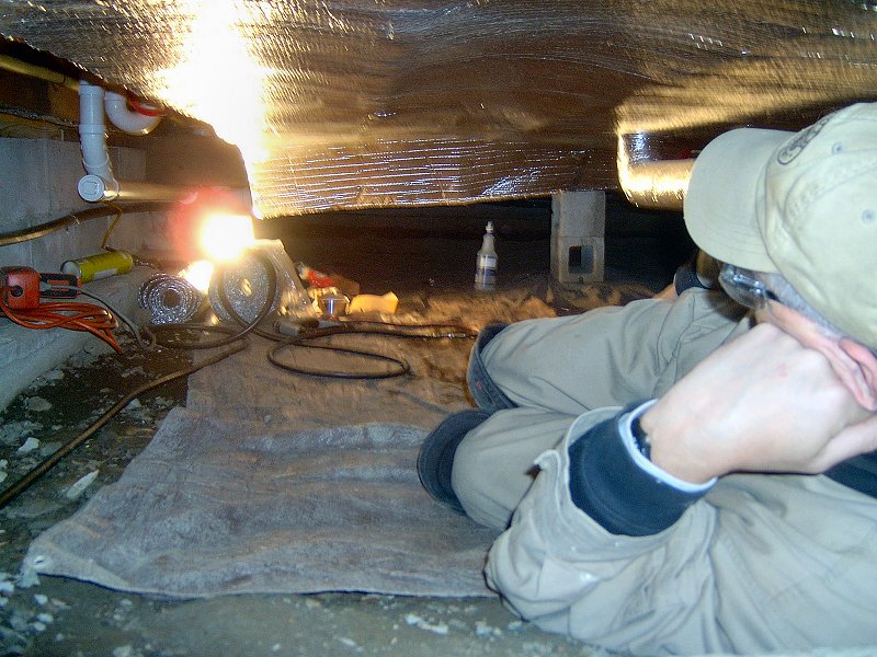
No really - after having played around under the house for a year, dragging this blinding, 500-watt worklight around to see, I finally
bought a little battery operated headlamp. I still used the big work light, but the headlamp was really nice to shed a little
extra light exactly where it was needed. That's when I noticed something that shouldn't have been there, and found the reason the floors
in the main house weren't as warm as the genkan. I'd pretty much spent most of the time under the house working
on my side while I bored holes and threaded tubing. The only time I worked flat on my back is when I was doing heat plates and insulation.
For the heat plates, I was usually working with my arms over my head, and with the insulation, I had the insulation spread out between
me and the floor most of the time. The point is, I rarely had a well-lit, straight up view of the bottom of the floor. I was flat on my
back and working on some insulation with the headlamp on, when I caught a glimpse of a little reflection from the bottom of the floor above me.
Huh? That can't be right.
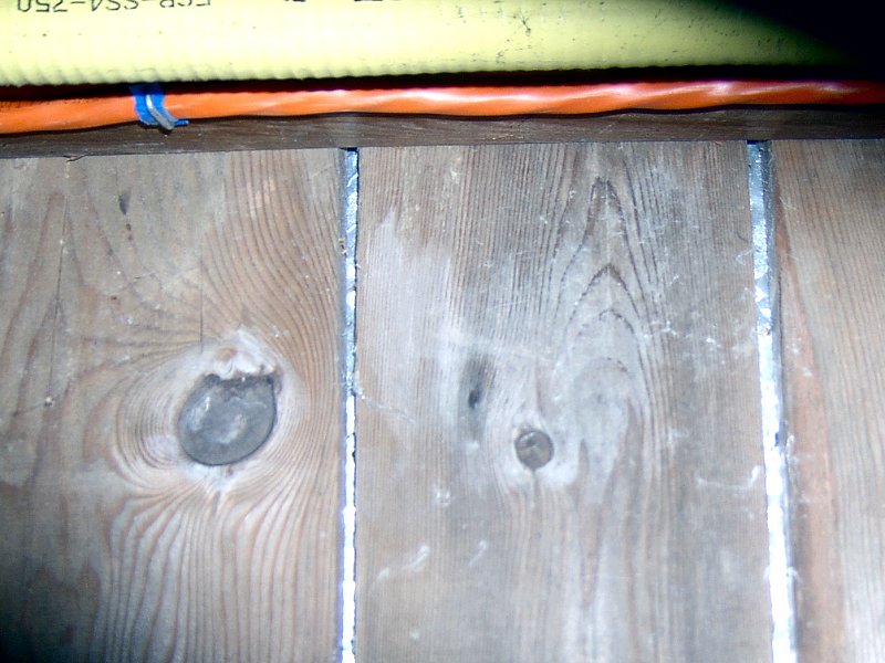
Yep, it was a reflection all right. The floors in the old porch were just 5/4 T & G subfloor boards - there had never been a finished floor in that part of the house. The radiant heat out there worked like it was supposed to, warming the floor layers and then the rooms above. The rest of the house had finished floors of linoleum tile applied to 3/4-inch plywood. The plywood was nailed to 3/4" planks that were nailed to the 2 x 8 floor joists. The planks had little 1/8-inch wide gaps between them and I was seeing my headlamp reflect off of some foil that was above the planks facing down. A year into the radiant floor heat installation, and it was all for naught. Remember, the way you insulate radiant heat is with foil, and as I was installing the last of the insulation I find most of my floors have a foil moisture barrier in them. As I later learned when I removed the kitchen floor, the original builder put down the planks, then rolled out some sort of foil faced kraft paper, covered that with tar paper, then put down the plywood for the linoleum. One of the main reasons I'd made the decision to install under-floor heating rather than use the pre-grooved, aluminum cored floor panels was because I didn't want to go through the mess and difficulty of tearing up all the linoleum and plywood flooring inside the house. With all the heating finally installed, I was going to have to do exactly what I set out to avoid doing in the first place if I wanted the heating system to function properly.
 Nearly done, at last.
Finishing the Radiant Floor Heat
I discovered the foil-in-the-floor mess back on 2007, and while it was certainly bad news, the reality is that it just adds one more
task to the seemingly never-ending home renovation project. Part of me was relieved to finally make sense of why the heat in the main
house was noticeably different than the genkan. Despite the need to remove all the floors inside at some point,
I still needed to finish doing the foam sealing and final bits of insulation under the house. Most of it was done in 2007, but I
couldn't say it was really finished until I had everything else done under the house. Any penetration through the floor would mean more
work under the house with stapler, tape and foam. We did the plumbing work over the Fall and Winter of 2008, and I finally got back
under the house in the Fall of 2009 to fix the insulation I'd tacked up after we did the plumbing, then get everything sealed up. I'll
still need to break into the insulation to install a floor plug in the living room, and grab a coax and phone line for the bedroom,
but I've got those areas marked and all the wires are in place already - shouldn't be a big deal.
So we know the radiant floor heating system actually works, and we're very happy with it. It's not the same as forced hot air to be sure - if you're cold, turning up the thermostat doesn't really make a difference for about a day. Folks have said radiant floor heating is noisy, with lots of creaks and pops as things expand and contract. It's true that there is some noise when the system first comes on. There's a little creaking noise here and there as the tubing expands inside the heat plates and around some of the tighter bends, but it's over in a few minutes (and I kind of like it - reminds me of the noises that big old wooden boat made under sail at night). It only makes noise when it comes on after having been off for a while, and there's no noise at all during normal operation and temperatures outside remain cool. Oh, and the kitchen and bathroom floors have been worked on for other projects since I first noticed the foil, so there's no foil in those anymore... nice and toasty now.
The New Boiler
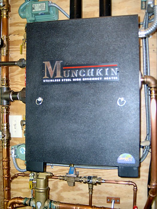
The boiler from Keyspan sat there in the crate while I re-built the porch around it for a year, then started thinking about where I was going to install the beastie (it's about the size of a washing machine). I'd gotten the old floor furnace running on natural gas (we'd already had the gas installed when I got the replacement parts to repair it, so I just got the parts for N.G. instead of the original LP gas), and the neighbor had installed a used N.G. hot water heater as a temporary fix until the new boiler was installed. I knew the general location for the new boiler, but in order to get all the stuff I wanted into the utility room I was quickly running out of space and losing kitchen and entryway square footage. That's when my neighbor told me about a fairly new product on the market - the Munchkin™. No, not the little fellows in blue suits singing about the yellow brick road...
 The installed Munchkin™ T80M (4 photos).
Munchkin™ boilers are ultra high-efficiency, fully modulating, stainless steel boilers made here in Massachusetts by Heat Transfer Products, Inc.. While the Keyspan supplied Burnham Revolution® is a fine conventional cast iron boiler (87.6% AFUE), it was awfully big, and I was having a very difficult time figuring out where I was going to put the thing. The Munchkin™, on the other hand, is tiny in comparison - 24-inches tall, 12-inches deep and 16-inches wide, weighing in at just under 60 pounds (it can be hung on the wall). More importantly, the Munchkin™ operates at a staggering 95.1% AFUE. It's so efficient, the vent pipe is PVC plastic, rather than double-walled steel. The "ultra high-efficiency" is achieved by the "Vision 1" control system, which monitors return water temp, supply water temp, indoor air temp and outdoor air temp, then adjusts the boiler fire rate to reach the thermostat set-point (rather than just turn itself on and off repeatedly - or "short cycling") when heat is called for. Of course all that high efficiency and stainless steel comes at a fairly steep price tag, and we already had a new boiler sitting in a crate that had cost us nothing.
Installing the Munchkin™ Boiler: Spring 2006
I talked with the plumber about how well the Munchkin™ would work for our project to see if he had any customers in the market
for a new Burnham... He said he was developing a couple condo units, and that he'd swap my Burnham boiler to that project, then I could
pay him the difference in the value of the Burnham and the cost of the new Munchkin™ in order to get us our new boiler. We did
the deal, and in late Winter of 2006 he dropped off the new T80M boiler as I was getting the utility room finished up.
As we'd done with most of the plumbing related tasks on the project, I was responsible for doing as much prep work as possible,
then the plumber would stop by and do his thing when everything was ready. I did the wiring for the boiler and circulation pumps,
mounted the boiler on the wall, and installed the fresh air intake and vent stack through the attic. When I had all that done, the
plumber came back with his nifty Viega ProPress®
![]() tool and bags of fittings. Within
a couple hours he had the boiler operational, although it was just running the indirect hot water heater until I finished installing the
radiant heat tubing under the floor (see above). Opening the valves to enable each heat loop was taken care of by him on later visits.
When he'd finished installing all those new copper pipes and fittings, I commented on how nice it all looked. He said I should polish
all the tubing with some Scotch-brite, then clear coat it (he was joking). When he left, I polished all the copper with Scotch-brite, then
gave everything a few coats of clear lacquer, naturally.
tool and bags of fittings. Within
a couple hours he had the boiler operational, although it was just running the indirect hot water heater until I finished installing the
radiant heat tubing under the floor (see above). Opening the valves to enable each heat loop was taken care of by him on later visits.
When he'd finished installing all those new copper pipes and fittings, I commented on how nice it all looked. He said I should polish
all the tubing with some Scotch-brite, then clear coat it (he was joking). When he left, I polished all the copper with Scotch-brite, then
gave everything a few coats of clear lacquer, naturally.
Heating System Maintenance & Repairs
Trouble with the Munchkin™: Spring 2016
We got a good 10 years from the Munchkin™ without paying any attention to the thing at all (which wasn't necessarily the right
thing to do… ) then in early 2016 the thing had enough of being ignored, and started tossin' up fault codes (F09, F10, and
occasionally F18) on the Vision 1® control display. We'd hit the re-set switch and it would run okay
again for a day or two, but then it would pop up another fault code (most frequently the F18 "Gas Valve Error" code). My
neighbor the plumber that had installed the thing came and took a look, then got on the phone with a support tech from Heat Transfer Products.
The said it was likely due to a bad gas valve harness assembly, so I ordered one of those and installed it a week later when it showed up.
The thing still stopped working with fault codes, so after another call and a bit more troubleshooting they determined that it was
most likely that something had happened to the control board, and recommended replacing that. We did that, and the thing worked well enough
for the rest of the Spring and all through that Summer (it only fires for the indirect hot water system in the Summer, so no real
test with that).
That Fall when we got into heating season again, more trouble came up in the form of a really noisy circulator pump. We had originally
installed a Taco® 00R-IFC® Radiant Heating Circulator as the "zone circulator"
pump, and it had started chattering like crazy whenever the system fired-up. Rather than go back to the neighbor again, I decided to
try another HVAC contractor we knew through church (Covenant
LLC![]() ). They sent their guy out and
he shut down the system to investigate the pump. The check valve was a crusty mess, and the boiler fluid was also black. He installed a new
Taco® Viridian® VR1816 Circulator, then gave the system a pretty good flush and
purged the air to get things working well once more. He also replaced the spark electrode and gasket, which had never been done (and
is supposed to be checked or replaced every year). The work Covenant did got us through a couple more years without any more fault codes
or other problems, until we got into the heating season for Fall or 2019.
). They sent their guy out and
he shut down the system to investigate the pump. The check valve was a crusty mess, and the boiler fluid was also black. He installed a new
Taco® Viridian® VR1816 Circulator, then gave the system a pretty good flush and
purged the air to get things working well once more. He also replaced the spark electrode and gasket, which had never been done (and
is supposed to be checked or replaced every year). The work Covenant did got us through a couple more years without any more fault codes
or other problems, until we got into the heating season for Fall or 2019.
Another Bad Pump: Fall 2019
At the start of the Fall heating season, we noticed the boiler was making a rattling noise again at start-up, so there was probably air
in the system or another check valve had failed. After a closer look, I noticed there was water dripping from the back of the "call-for-heat"
pump. This was the Taco® "00"® Series 7 Pump that had been installed originally
back in 2006. I gave Covenant a call again, and they sent the same fellow out to have a look as had been here before (really nice guy, and he
was quite familiar with our set-up by now). He shut down the system and isolated the plumbing around the pump to remove it and have a look.
This pump was even worse than the other one — not only was the check valve a mess, but the impeller had rubbed on the cast iron pump flange
unit and actually worn through the cast iron (which was the source of the water leak, not a bad flange gasket as I had thought).
He only had a Taco® 0015e® ECM High-Efficiency Circulator on the truck, so
even though it's a bit larger than what we needed, he got that installed to replace the old "007". The new ECM pumps are adjustable,
so he set it to a low speed, then bled the system and all was well again.
That "0015e" only lasted a couple months before it started chattering like crazy every time it was running. We had enough of the rattle by early 2020, so we called up Covenant again to see if they could come do a warranty swap on the thing. The usual guy showed up again, pulled the noisy "0015e" and replaced it with a properly sized Taco® 007e® ECM High-Efficiency Circulator. Another flush and bleed of the system, and we had trouble free heating for the rest of the season.
More System Troubles: Winter 2020-21
Every once in a while in the Fall of 2020 the Munchkin™ would shut down again with a fault code F10 — "Loss of Flame Signal".
Another call to Covenant and our usual guy showed up once more. He pulled the flame rectifier probe and cleaned it, and the thing worked
a little better but still wasn't right. He also noticed there was no "probe hole" in the flu pipe, which is supposed to have a little
3/8-inch hole with a plug screwed into it where the installer inserts a combustion analyzer to set the gas valve during initial start-up.
The neighbor had apparently never done that when he installed it, which likely contributed to all the problems we'd been having. The Covenant
guy did a little rough adjustment of the flame by just looking through the burner's site glass, but he seemed to think it just wasn't getting
enough fuel. He had to get his combustion analyzer calibrated before we could use it, so he said he'd give a call when he could return. In
the mean time I ordered a little stainless steel pipe plug, then drilled and tapped the flu pipe for that. I also got ahold of National Grid
to have them come check our gas line and verify we had sufficient pressure and volume available. The National Grid guy showed up a couple days
later, and while we had a relatively new gas meter (they have to replace it every seven years in Massachusetts to ensure it's safe and
accurate), the gas pressure regulator had been in place since gas was installed in 2005. His tests showed it was still within spec, but
just barely. He changed it out for a new unit, and lo and behold, that was the last time we had a fault code on the Munchkin™. The
Covenant fellow got his analyzer calibrated, and came by to double-check the gas valve adjustment. A little tweak and it was running better
than ever.
Not long after that however, I found another drip coming from around the Taco® Viridian® VR1816 pump that had been installed in Fall of 2016. Covenant returned again, and pulled that pump to investigate — the impeller had worn through the cast iron flange unit again. He swapped out the flange (but kept the same pump motor wired in place) and the leak was no more.
The Final Repair?: Winter 2021-22
The system was running well with the relatively new pumps in place and the combustion mix finally set properly, but it would still make
a chattering noise for a few minutes on start-up. Since the "zone circulator" motor hadn't been replaced (we had only swapped out
the worn flange the year before), I thought perhaps that was the source of the noise. Rather than call Covenant yet again, I was determined
to take care of this noise myself. The first thing I did was try to really isolate each section of the system and do a proper flush to remove
any air that may be trapped. While working my way through the various loops, I found the lower drain valves for some of the sections
were actually plugged with crud ( most likely this was cast iron "dust" that had collected when those pump flanges were getting
worn down". I poked a stuff wire into the open valve and got the crude out, then I flushed the system until the liquid ran clear.
I'm not concerned that there's basically no Glycol left in the system — when power goes out we run it with a generator, and if
it were to freeze due to an outage when we're not home, the PEX would just expand and nothing would burst. Anyway, while pokin' the crud
out of one of the drain valves, I found a little, light gauge spring in with the crud. I figured the only place that could
have come from was the valve inside the Spirovent® "Air Eliminator" unit above the expansion tank.
If that thing wasn't working, it would explain why we still had noise from the system due to trapped air!
I ordered a new "vent head" for the Spirovent® (and the "inner core" screen, since that was really crusty too), and also decided to get a complete new Viridian® VR1816 pump to replace that mis-matched pump and housing that had been installed the previous year. In the Spring of 2022 I made time to work on the system, and re-built the Spirovent®, then installed the new pump. A thorough flush of the system to do my best to get the air out, and the whole thing has been running silently ever since. Hopefully this will keep going for years to come
More Munchkin™ Troubles: Winter 2025-26
I noticed late in the Summer of 2025 that the pressure/temperature gauge in the main output line from boiler was startin' to look pretty crusty.
Apparently it had some tiny leak inside of it, and had about a quarter inch of liquid in the bottom along with the paint on the gauge face starting
to bubble and peel. I ordered a replacement gauge, as well as a new "Ceramic Target Wall", as I'd noticed that thing was a bit crumbly
the last time I had cleaned out the combustion chamber. I never found the time to shut the thing down and install the parts before heating season
arrived for Winter 2025-26, so I figured the work will wait until later in 2026. The Munchkin™ had other ideas...
It was working just fine, even though the gauge didn't do anything anymore, but then we started to get in to some real cold weather in January of 2026. Every once in a while we'd awaken to a bit of a chilly house, and upon inspection the boiler controller would have a F01 fault code indicating "Vent Temperature Limit Exceeded" and had shut itself down. I'd hit the re-set on the limit switch, then the thing would restart and run fine for a few cycles without any problem, but then pop up that F01 fault again and shut down. After a bit of research, one likely issues (aside from actual flu temp. issues from a bad mix or a faulty switch) is that the ceramic for the target wall is damaged and causing the limit switch to trip (since this limit switch is right at the exhaust pipe base, directly above the target wall). I know my target wall ceramic is in rough shape, so I figure replacing that will take care of this fault later this year. In the mean time, I found that if I simply run the thing with the boiler cover removed (the front/top of the plastic box - not any of the actual metal boiler components), the limit switch gets enough air flow that it no longer trips. Problem solved for now.
Then in early February while workin in my office, I heard a dripping noise coming from the boiler room. I checked all the piping and found there was a drip from the back of the Taco® 007e® ECM High-Efficiency Circulator (the "CH" pump) that we had replaced back in the Winter of 2019-20. It appeared to be leaking from the lower flange, so I put a little bucket under it and figured I'd replace the flange gaskets when I get into the system to do the gauge and ceramic thing later this year. That notion lasted about two days, and I found the bucket had overflowed one night and water was spraying against the wall from the back of the pump. I shut everything down and pulled the pump, only to find the same thing had happened to this that had happened to it five years ago – the cast iron flange/impeller housing had simply deteriorated away and had a couple pin-holes where water was spraying out of the thing. The pump motor and check valve were fine, but the cast iron had failed. I checked a few plumbing supply places online and noticed that Taco® is now offering these pumps with a stainless-steel flange/impeller housing unit (for more than twice the cost of their cast iron units), but no one has the stainless-steel version in stock around here. A run to Home Depot for another 007e® ECM High-Efficiency Circulator and I was back in business in less than an hour. I'm thinkin' I might replace that new-ish Viridian® VR1816 we installed in Winter 2021-22 with a stainless-steel version this Summer, since it looks like about five years is all I should expect before that cast iron flange rots away and starts leaking.
Indoor Air Quality & Ventilation
As we've been making progress on our home renovation, we've slowly been making the house "tighter" - new energy efficient windows and
doors, housewrap, caulk, spray foam, insulation, etc. are all employed to reduce our energy costs by eliminating outside air infiltration.
However, all those measures also have the potential to reduce our Indoor Air Quality (IAQ). There's no shortage of pollutants in a typical
home that adversely affect IAQ (have a look at the EPA's IAQ House Tour
![]() for more information), so the goal is to
find a manner of ventilation that allows us to maintain an energy efficient home, while addressing IAQ.
for more information), so the goal is to
find a manner of ventilation that allows us to maintain an energy efficient home, while addressing IAQ.
It's a tricky balancing act... maintaining the energy efficient bit seems simple enough - seal and caulk every possible crack and seam in the building shell - the tough part comes with that pesky IAQ problem. Vent fans that exhaust indoor air to the outdoors don't really do much for improving IAQ if they don't have a means of obtaining "make-up" air. In other words, if the bathroom fan is rated to exhaust 150 cubic feet per minute (CFM) but I place it in a sealed room, it's not going to work very well as it sucks all the air out of the room then just makes noise. It's a simple vent fan, not a vacuum pump. A proper ventilation system should remove stale air and indoor air pollutants from the home while it distributes fresh, filtered and conditioned air throughout the home at the same time. The good news is that such a thing exists: it's called an air-to-air heat exchanger, or Heat Recovery Ventilator (HRV).
Planning the Ventilation System: Fall 2005
After researching IAQ issues, mostly through the EPA (I highly recommend spending some time looking over their IAQ pages, I found them
very informative and I'm glad I dove into it during the planning stages of our project), we decided to add an HRV to our plans for updating
the mechanical systems. The HRV is an octopus of ductwork connected to a box that houses a heat exchanger and filter unit. Stale air
exhaust vents are placed throughout the home and ducted to the box which contains an exhaust fan, and that fan pulls the exhaust air
through the heat exchanger then vents it outside. Another fan in the box pulls fresh air from outside through the heat exchanger, then
distributes that air through ducts to fresh air vents throughout the home. The idea is to constantly replace the stale air with fresh
air, and to condition the fresh air to the inside temperature by passing it through the heat exchanger. A properly balanced HRV will
transfer around 75% of the heat from the exhaust air to pre-warm the incoming fresh air.
 The HRV duct layout.
With the decision made to install an HRV, I then determined how much ventilation we would require in order to have a positive effect
on our IAQ. To determine the proper size HRV for our needs, I used the basic calculation for a residential whole house air exchange
rate of 0.35 air changes per hour (ACH) , but no less than 15cfm per person as specified by the American Society of Heating, Refrigeration
and Air-Conditioning Engineering (ASHRAE) in its Standard 62.2.2007 (available through the
ASHRA standards page
![]() ). First I calculate the total volume of
air in the house (912 sq. ft. x 8 ft. ceiling = 7,296 cu. ft.), divide by 60 minutes (121.6 cu. ft./min.), then multiply by the air exchange
rate (121.6 x 0.35) to get 42.56cfm. Proposed changes to 62.2 recommend relying more on occupancy and square footage calculations
rather than a cookie-cutter 0.35ach method (since many IAQ issues are a result of the number of occupants, rather than just the
size of the structure). Using the 15cfm per person (which may also be calculated as 2 persons for the first bedroom, and 1 person for each
additional bedroom) occupancy method would put the needed capacity at 30cfm, then adding the 62.2P recommendation of an additional
2cfm/100 sq.ft. raises that to 48cfm total.
). First I calculate the total volume of
air in the house (912 sq. ft. x 8 ft. ceiling = 7,296 cu. ft.), divide by 60 minutes (121.6 cu. ft./min.), then multiply by the air exchange
rate (121.6 x 0.35) to get 42.56cfm. Proposed changes to 62.2 recommend relying more on occupancy and square footage calculations
rather than a cookie-cutter 0.35ach method (since many IAQ issues are a result of the number of occupants, rather than just the
size of the structure). Using the 15cfm per person (which may also be calculated as 2 persons for the first bedroom, and 1 person for each
additional bedroom) occupancy method would put the needed capacity at 30cfm, then adding the 62.2P recommendation of an additional
2cfm/100 sq.ft. raises that to 48cfm total.
I decided on the Fantech![]() model VHR1404r (the "r" means it comes with an additional re-circulating vent to run a self-defrost mode when outdoor air temperatures
are consistently below 23° F, so the unit doesn't ice-up from internal condensation), then got busy trying to figure out where to
put it and all the ductwork. While doing all this research into IAQ and ventilation, we also planned to add a 300cfm (max)
range hood as part of the over-the-cooktop microwave, and a Fantech PB100F, remote-mount 100cfm bathroom exhaust fan / CFL light
combo for the shower.
model VHR1404r (the "r" means it comes with an additional re-circulating vent to run a self-defrost mode when outdoor air temperatures
are consistently below 23° F, so the unit doesn't ice-up from internal condensation), then got busy trying to figure out where to
put it and all the ductwork. While doing all this research into IAQ and ventilation, we also planned to add a 300cfm (max)
range hood as part of the over-the-cooktop microwave, and a Fantech PB100F, remote-mount 100cfm bathroom exhaust fan / CFL light
combo for the shower.
 The installed Fantech HRV (2 photos).
Installing the HRV: Fall 2005
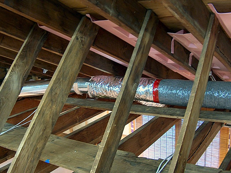
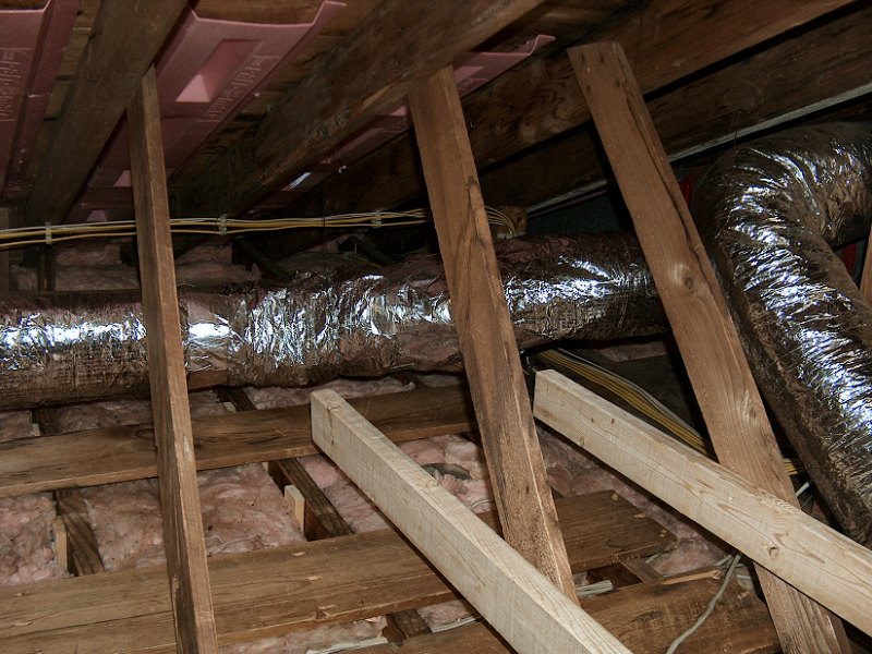
The first pair of supply and exhaust duct runs went into the renovation project very early, since they had to be installed above the
genkan ceiling while the old porch was getting rebuilt. As shown in the plan above, I placed an exhaust vent
in my little office (yes, I have a smoke from time to time when sitting at the computer), and a supply vent in the lovely bride's office
to ensure she doesn't have to deal with my smoke. The rest of the duct connections were installed above the utility room, with the
HRV intake air coming from under the front porch roof and the exhaust directed to an 8-inch roof cap on the back of the
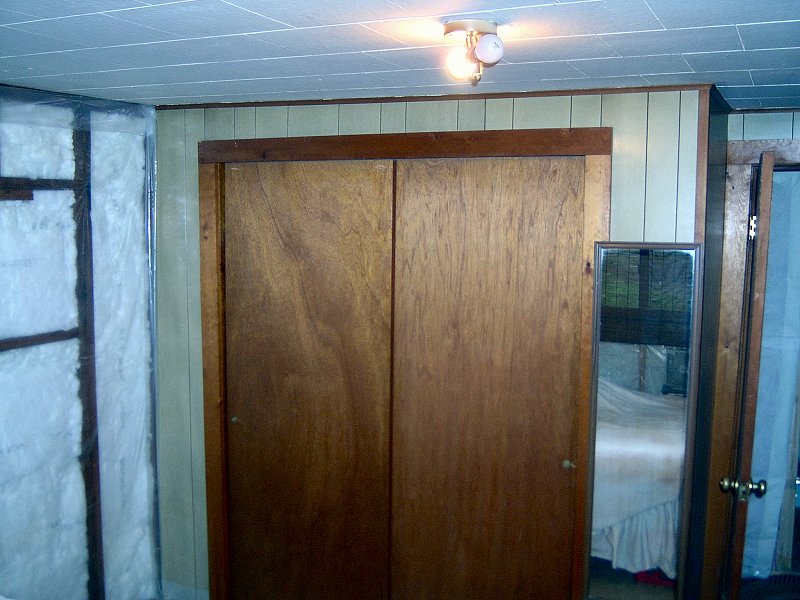
genkan roof. The re-circulation air intake was placed high in the wall above the coat closet. The duct runs
from the HRV to the main house have been capped-off at above the kitchen, and will be completed after the ceiling is replaced and
insulated in each room. All ducts and duct fittings are galvanized steel, and all seams and connections are taped on the outside and
sealed with mastic on the inside. I also insulted all ductwork with insulated flexible duct - it just slides right over the steel and
is a lot easier to install than trying to wrap all the runs with little strips of fiberglass.
The HRV is controlled with a Fantech EDF-5 "Intellitek" Multi-Function Wall Control mounted in the kitchen, and a Fantech RTS-2 Override Timer in the laundry room. The EDF-5 is set to cycle the HRV for 20 minutes per hour at low speed in "standard mode", removing stale are and supplying fresh air. It also automatically indicates when the unit is in defrost / re-circulate mode, as well as indicates when the filters should be cleaned. The EDF-5 may also be used to manually override the pre-set cycle timer and run the unit continuously if needed. In addition to the timer and manual modes, the controller may be set for humidistat mode which monitors interior relative humidity, then kicks the HRV into high-speed mode if the relative humidity rises above a user-set threshold. The RTS-2 is a simple single button wall-switch that runs the HRV on high-speed for 15 minutes when pushed - it's installed in the laundry room so the HRV can be engaged when opening the washing machine after a load of wash to remove excess moisture from the laundry room.
 Magnehelic Differential Pressure gauges.
Balancing the supply and exhaust fans within the HRV is critical for the unit to operate properly, and I had a bit of fun with that.
I think the usual method is to hire an HVAC professional to use his air-flow measuring equipment and balance the fan speeds, then crawl
around in the attic and fiddle with dampers. I could do that... once I had some air-flow measuring equipment, of course. I'd
need a
Dwyer® Magnehelic®![]() differential pressure gauge, a little tubing, and a portable pitot tube to stick into a duct run and measure air flow. When I started
checking out gauges and saw how cool they were, I went a little overboard (what a surprise). Magnehelic®
gauges are fairly expensive, depending upon the range of the gauge. Then I found them on E-Bay. The first one I bought was a little
kit that included a gauge, rubber hose and tube, gently used, for about $10. It worked, but the low air-flows of the fans in my HRV
barely bumped the needle. I gave it to my neighbor the plumber, even though he doesn't do much with forced-air systems any more.
Now the search was on for the proper ranged gauge. The next one I managed to win was a very nice dual gauge (inches of water and feet
per minute) with a 0-0.5 inch range. It hovered around mid-range with a fan on high, so that was the one. It only took a few days to find a
second one, but after searching for a couple weeks, I had to settle for a non-dual readout third unit to use for the re-circ duct. I
permanently mounted all three gauges on the wall next to the HRV, with little PVC tubes running up the wall and through the ceiling to
connect to the pitot tubes mounted in the appropriate ducts. With the gauges right next to the HRV, it was very simple to balance the
flow properly. I also gave the system a little "extra" flow on the supply fan to give the whole house a bit of positive pressure.
That should help prevent a negative pressure effect when the kitchen or bathroom exhaust fans are running.
differential pressure gauge, a little tubing, and a portable pitot tube to stick into a duct run and measure air flow. When I started
checking out gauges and saw how cool they were, I went a little overboard (what a surprise). Magnehelic®
gauges are fairly expensive, depending upon the range of the gauge. Then I found them on E-Bay. The first one I bought was a little
kit that included a gauge, rubber hose and tube, gently used, for about $10. It worked, but the low air-flows of the fans in my HRV
barely bumped the needle. I gave it to my neighbor the plumber, even though he doesn't do much with forced-air systems any more.
Now the search was on for the proper ranged gauge. The next one I managed to win was a very nice dual gauge (inches of water and feet
per minute) with a 0-0.5 inch range. It hovered around mid-range with a fan on high, so that was the one. It only took a few days to find a
second one, but after searching for a couple weeks, I had to settle for a non-dual readout third unit to use for the re-circ duct. I
permanently mounted all three gauges on the wall next to the HRV, with little PVC tubes running up the wall and through the ceiling to
connect to the pitot tubes mounted in the appropriate ducts. With the gauges right next to the HRV, it was very simple to balance the
flow properly. I also gave the system a little "extra" flow on the supply fan to give the whole house a bit of positive pressure.
That should help prevent a negative pressure effect when the kitchen or bathroom exhaust fans are running.
HRV Ductwork Installation: Winter 2023
As mentioned above, the ductwork for supply and exhaust air from the HRV and to our office areas was installed while building out the
genkan back in 2005. Although I can hardly believe it's been
18 years since that was done, we're finally able to make some progress on the ductwork for the rest of the house now that the
living room ceiling work is underway. The air supply ducting and outlet to the bedroom was
installed when the old front porch was removed, so now I need to get that bit of ducting connected to the living room run, living room
supply outlet, and then over to the HRV. Rather than try and crawl around at the edge of the attic to get this stuff done, it's much easier
to work on it from below while the living room ceiling is open.
 The HRV fresh air duct runs (4 photos).
The two fresh air outlets are located fairly close to the South wall (take a peek at the plan, above), although I did relocate the bedroom supply from the center of the wall over to the Southwest corner. The living room supply will be centered as planned, and I located it in-line with the two recessed light fixtures along that wall. The other change from the plan was that rather than use tee connectors to go from the main line to the duct, I found some nice 45° wye connectors from Lowe's the will provide better airflow than the tees. Everything was connected with the usual self-drilling screws, ductseal, and fiber-reinforced foil tape, and then covered with insulated flexible ducting. A short, straight piece out of the wye got me to the 45° corner, then it was straight across the attic (now that I know the actual height of new attic floor) and up to the supply connection over the boiler room. The ductwork for the exhaust inlets in the kitchen, bathroom, and laundry room will likely get done in a few weeks, as I'll need to re-arrange a bunch of stuff stored in the attic to get access to where those will be installed. At least the exhaust runs and outlets are all going to be centered in their rooms (the kitchen and bathroom outlets are already in place), so the duct runs will be closer to the center of the attic and much easier to assemble from within the attic.
Finishing HRV Ductwork: Late Winter 2023
With the living room ceiling mostly wrapped up by the end of February, I was able to then head back to the attic and start re-arranging all
the stuff up there to clear out the area over the kitchen, bathroom, and laundry room. All that stuff got temporarily re-located to over the
living room, which gave me enough room to get the rest of the HRV exhaust duct installed.
Installation began above the boiler room with a 45° down turn heading toward the kitchen outlet, which was connected with a 45° wye connector right above the kitchen ceiling. From that wye it was then another 45° connector to make the straight run over to above the bathroom, where things get a little more interesting…
 The HRV exhaust duct runs (3 photos).
The area over the bathroom was already a bit crowded, with the 8-inch duct for the kitchen stove exhaust coming up right above the wall between the kitchen and bathroom. That wall also has the vent stack plumbing for the all bathroom, kitchen, and laundry drains running right above it. The area also has the 4-inch flex-duct for the attic mounted bathroom exhaust fan. Getting a 6-inch straight duct through all that and connecting it with another 45° wye connector for the bathroom ceiling was going to be a bit tricky. The straight pipe "sorta" fit through the available space, but it needed a little modification to really make it work — which meant I just dented the duct piece in a bit to fit by the 8-inch duct near the top, then dented it in a little to fit by the vent stack pipe a bit further along on the bottom. Both ends stayed round, so it still connected up fine (and the insulation covers the dented sections anyway). Just past the vent pipe I then connected another 45° wye for the bathroom exhaust vent, followed by a 45° elbow to run the duct a little closer to the back wall. A couple feet of straight duct connects to the last 45° elbow, with a 5-foot piece of 6-inch duct along the back wall to the center of the laundry room for the last exhaust vent fitting in the center of the ceiling in there.
HRV Installation Completed: Late Winter 2023
With all the duct work installed at long last, the final HRV installation tasks were to get the RTS2 override timers connected, then balance
the system. The override timer in the laundry room had been installed and wired to the HRV years ago, and the timer in the bathroom was installed
with the wire run up to the attic a while ago as well. I only needed to run the bathroom wire up to the wire from the laundry and join those together with
a couple little blue wire nuts (this is a simple 24VAC circuit with thermostat wire, so I'm not bothering with junction boxes for this stuff). I then
squeezed into the space in the attic near the boiler room and used a yardstick to reach the lever on the duct dampers. The lovely bride hit the override
switch in the bathroom (which turns the HRV on at high speed for 15 minutes) and took a look at the magnehelic gauges to see how the balance looked. The
exhaust gauge showed about 2100 feet per minute (FPM, which in this case is about .27 inches of water), with the intake showing around 1900FPM (about
.22 inches of water). That was pretty close, but I prefer to set it to provide slight positive pressure in the space. Both dampers looked to
be closed just a tad, so I tapped the lever a couple times on the intake to get it fully opened, and did the same to slighty close the exhaust damper. That put the
intake up to 2000FPM (about .25 inches of water), and put the exhaust at 1800FPM (about .25 inches of water). That'll do nicely.
Air Conditioning
We went for years without any type of air conditioning, then one very hot Summer I broke down and purchased a little 5,000Btu window unit. It doesn't get that hot here that often, but when it does, sleeping isn't really an option. The window unit was plenty to do the trick and make Summer nights bearable, but with our new sliding windows there's no way to install a window air conditioner. We gave the unit to a friend, and I started looking in to some manner of central air-conditioning unit as a replacement.
Since we don't have a forced-air heating system, we don't have ducts running to every room to just connect an A/C unit to. It would
still be possible to hang a stand-alone central A/C unit in the attic, then run conventional ductwork to all the rooms, but things are
pretty crowded up there already and I'm not all that interested in filling the remaining attic space with an A/C unit, plenum chamber
and branch ducts. The plumber is a big fan of small-duct, high-velocity A/C (the most familiar version is
The Unico System®
![]() , although a number of manufacturers
make a similar product). It makes sense, and it's a very reasonable option for a retrofit installation, however it's pretty expensive, and
it just feels like way more A/C equipment then we need. We really only use the thing for a couple weeks in August, and then it's generally
just at night. On the other hand, if I've got central air, I'd probably leave it on all the time from July to September - or at least until
I get the first electric bill after running the thing for a month.
, although a number of manufacturers
make a similar product). It makes sense, and it's a very reasonable option for a retrofit installation, however it's pretty expensive, and
it just feels like way more A/C equipment then we need. We really only use the thing for a couple weeks in August, and then it's generally
just at night. On the other hand, if I've got central air, I'd probably leave it on all the time from July to September - or at least until
I get the first electric bill after running the thing for a month.
The primary goal is to make the bedroom comfortable, so we've pretty much decided to go with a "mini-split" ductless system, most likely from Sanyo or Mitsubishi. We would mount the air handler on the inside of the West wall of the bedroom. That would allow us close up the bedroom and the air handler would just cool that room, or open all the sliding doors and let the thing blast the whole house. The only problem I'm having in making the selection is that I'm trying to find a properly sized unit that's got an Energy Star rating. Once most mini-splits get over 20,000Btu, the Seasonal Energy Efficiency Rating (SEER) takes a nose dive and they lose the Energy Star rating (the unit needs a SEER over 14.5 for Energy Star qualification, as well as to qualify for utility company rebates). I think we'll be able to get by with a 18,500Btu unit, so we should be fine. Lately I've been investigating the ceiling hung units too. They're a little more money, but they're quieter and not as ugly as a big plastic box hanging on the bedroom wall. The other advantage to the ceiling unit is that I can close off one of the vents, then add a duct off the plenum chamber in the attic for the closed vent to direct the airflow to a different room. That might be very handy to run a single duct out to the genkan, since that's going to be a tough area to cool with the sun streaming in the double glass doors all Summer.
For now, the only progress I've made on the air conditioner installation is to get a piece of 10/3 wire in place from the panel out to the Northwest corner of the house, where I'll have the compressor installed. I neglected to run that wire when I first installed the panel, but managed to snake it into place without having to tear up any drywall (it was one of the last things to go in the joist bays under the house before I finished the sealing and insulation in the Fall of 2009). Air conditioning isn't high on our priority list for the house project, although I'd like to get the electrical and plumbing lines that run from the compressor to the air handler installed in the walls while they're still open. I'll see what rebates and incentives are going to be available for 2010, then get an A/C contractor lined up for the installation (if I want the $500 rebate, I can't do it myself).
 Installing the indoor A/C unit (7 photos).
Air Conditioner Installation: Summer 2010
With the wiring in place and Federal tax credits ending in 2010, we decided to get the air conditioner installed this Summer.
After talking with a few contractors to get the bid process started, we decided to drop the Sanyo due to a poor service record
and go with a "Mr. Slim" mini-split ductless AC/heat pump unit from
Mitsubishi Electric
![]() . We selected the "M-series"
unit with both heating and cooling capacity, in the 15,000 btu size. We got six bids for the job, ranging in price
from $2,700 all the way up to $6,800, which is kinda crazy since the unit we wanted costs around $1,200. I liked the guy that
came in with the lowest bid, so we gave him a deposit and scheduled installation for just after the 4th of July holiday.
. We selected the "M-series"
unit with both heating and cooling capacity, in the 15,000 btu size. We got six bids for the job, ranging in price
from $2,700 all the way up to $6,800, which is kinda crazy since the unit we wanted costs around $1,200. I liked the guy that
came in with the lowest bid, so we gave him a deposit and scheduled installation for just after the 4th of July holiday.
Before the installer showed up, I had a fair amount of work to do to get ready for the install. The wire I had run last Fall was going to have to be moved because it would have put the compressor too close to the gas meter on the back of the house. Rather than splice another piece of 10/3 onto the existing wire (since there wasn't enough length to reach the new location), I went under the house once more and pulled down the insulation, then re-routed the wire in the joist bays so it would come out where we needed it with plenty of extra to work with. Inside the house, I had to remove the bedroom closet as well as the panelling and drywall on the wall between the bedroom and laundry room. That wall is getting moved eventually anyway, but I hadn't planned to tear any of that stuff apart just yet. In order to place the air-handler in the proper location on the bedroom wall (so it would be able to cool the whole house when the bedroom / living room fusuma doors are opened), that wall had to go or the air-handler would have been half way in the existing closet, which wasn't gonna make it. Once I had the bedroom wall down and cleaned up, I mounted a piece of plywood on the wall for the air-handler to mount to, and installed a 30A disconnect switch outside the house for the compressor hook-up.
 The outdoor A/C unit (6 photos).
Dave Stanley, from The Perfect Climate
![]() , showed up on time
on the day he promised, along with a helper, and got right to work. Within a couple of hours everything was installed
and we had air conditioning! The installation seemed to go very smoothly (not having to deal with drywall and having
the wiring in place probably helped), and the guys even pulled out the shop vac and cleaned up their mess without
being asked. We took care of the paperwork to ensure I could get the rebates and tax credits, then Dave went over the
controls with me and that was that. I must say the thing really works great - we ran it in "cool mode" for the first day
just to bring the temperature of the house down a bit, but ever since then we've just let it run in dehumidify mode and it's
keeping the house very comfortable.
, showed up on time
on the day he promised, along with a helper, and got right to work. Within a couple of hours everything was installed
and we had air conditioning! The installation seemed to go very smoothly (not having to deal with drywall and having
the wiring in place probably helped), and the guys even pulled out the shop vac and cleaned up their mess without
being asked. We took care of the paperwork to ensure I could get the rebates and tax credits, then Dave went over the
controls with me and that was that. I must say the thing really works great - we ran it in "cool mode" for the first day
just to bring the temperature of the house down a bit, but ever since then we've just let it run in dehumidify mode and it's
keeping the house very comfortable.
Of course, after the contractors were finished, I did a little additional "tweaking" to the installation - I didn't mess with anything major, but they left sealing the hole in the wall up to me (as I'd asked) so I took care of that and added some extra insulation to the refrigerant lines. I also re-routed the condensate drain to a better spot so I could get a weather cap over all the tubes and wiring where it comes out of the house. Having lived with central A/C now for a couple weeks, we're extremely happy with the decision to get it installed (especially since it's been an unusually warm Summer so far). The air-handler is incredibly quiet, and it's been doing a fine job. With the rebate and tax credit, we ended up spending less money to get the thing installed then if I'd bought the unit and tried to do it myself, so it worked out great.
Air Conditioning System Maintenance & Repairs
Noise from the Mitsubishi® Indoor Unit: Spring 2021
Just like the Munchkin™ boiler, the Mitsubishi® Mr. Slim® mini-split system
had hummed along without any problems for about 10 years. Every couple months I'd remove the air filters from the indoor unit and clean
them off, and every couple years I'd take the air compressor and blow gun to the outdoor unit to clear out any dust and leaves. However,
in the Summer of 2020, we started to notice the blower in the indoor unit was getting a little loud. I gave the Perfect Climate folks a call,
and asked them to come check the thing out and see if it needed any attention. Dave Stanley came by and took a look, but said everything seemed
fine. We just got used to the extra fan noise whenever we ran the thing in heat mode, and got on with it.
It didn't get used much for heating for the rest of the 2020-21 season, but when we fired it up in air conditioning mode in the Spring of 2021, the fan was really noisy and sounded like it was having trouble spinning. I dug around in the installation manual and figured out how to get at the motor (it's quite buried within the unit), then proceeded to take the thing apart to see if cleaning the fan and possibly giving a little shot of oil to the motor would take care of the noise. Then I screwed up big time…
I really know better than this, but I proceeded to start pulling the thing apart without turning off the power supply breaker. I have a little joke I like to tell folks when they're trouble shooting electronics: All that stuff you've heard about wires carrying electrons is hooey — those "wires" are actually little pipes that carry smoke, and the device runs on that smoke. How do I know that? Simple! If you ever "let the smoke out" the device will stop working! Science!
As I was working my way through the layers of plastic bits inside the wall unit, I found a metal shield screwed in place around the main
control circuit board. I pulled the shield cover, unscrewed the board, and swung it up out of the way to get at the motor bracket behind it.
Then I bumped the board while unscrewing the motor bracket, and it slipped back onto the metal shield which let the smoke
out of course. Idiot. I replaced the fuse on the board and tried to run the thing again (many of the various bits were
unhooked from the main unit, but their control cables were still connected), but it was cooked. I managed to find a replacement
control board online, so got that on-the-way while I finished getting the blower motor and fan out of the unit so I could give 'em a good
cleaning and lube. A few days later I had everything cleaned up (the cage fan was a real mess), and had received the new control
board. I re-assembled everything (with the power off this time) to give it a try, but even with everything cleaned up it was
still pretty noisy. It was going to need a new $150 fan motor. A week later and the new fan motor arrived (from the folks at
Younits.com![]() ,
which is also where I got the control board). I got everything put back together, and it's been running beautifully without a sound
ever since. Other than my $150 control board screw-up, I'd say running this thing for over 10 years with only a fan motor
replacement is a pretty good testament to the quality of these Mitsubishi® mini-splits.
,
which is also where I got the control board). I got everything put back together, and it's been running beautifully without a sound
ever since. Other than my $150 control board screw-up, I'd say running this thing for over 10 years with only a fan motor
replacement is a pretty good testament to the quality of these Mitsubishi® mini-splits.
↑
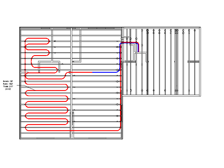
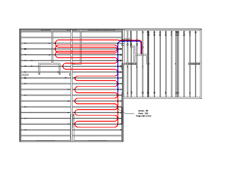
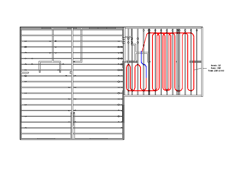
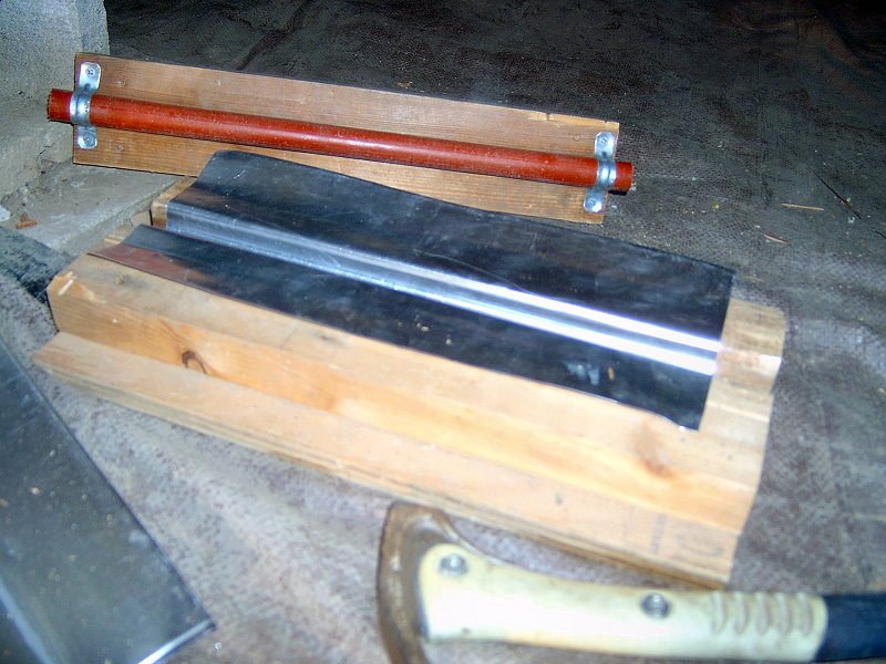
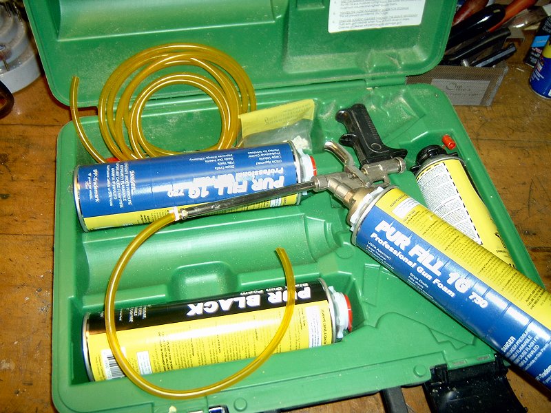
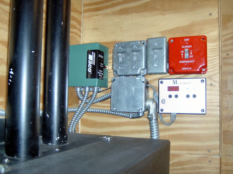
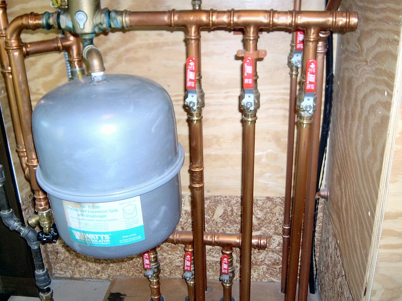
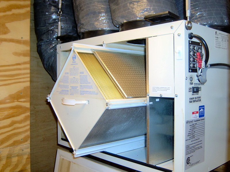
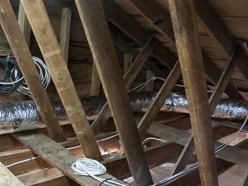
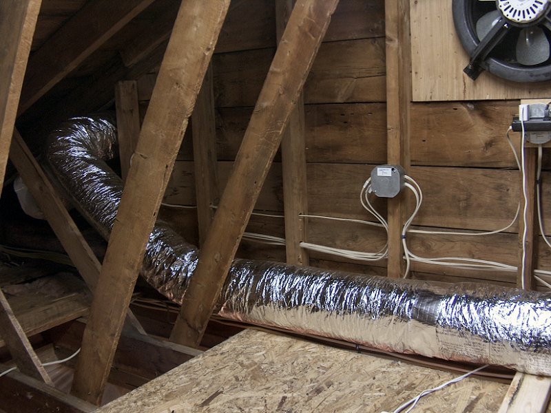
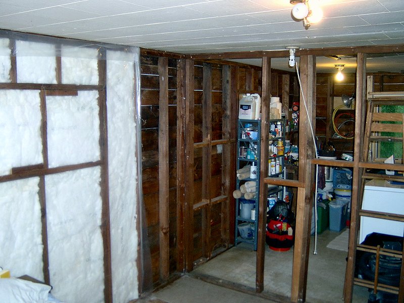
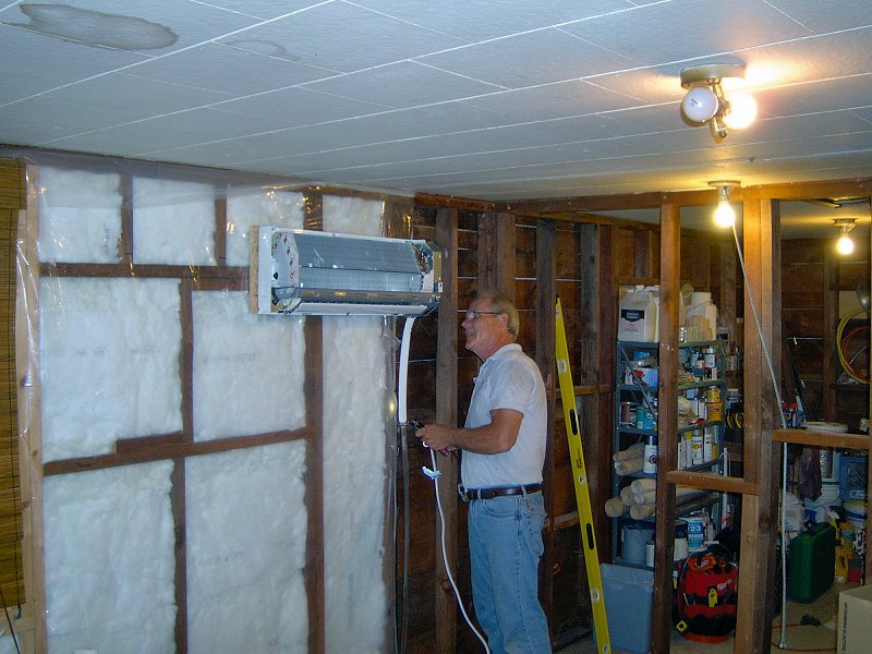
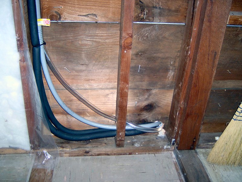
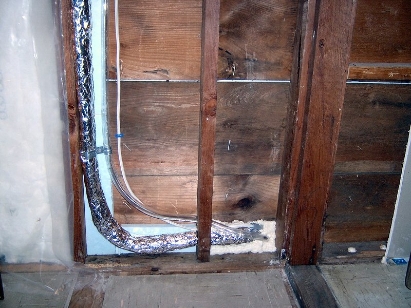
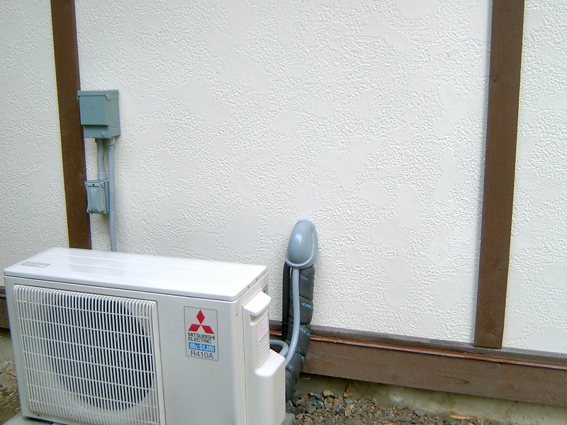
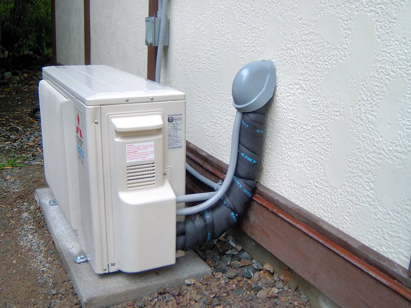
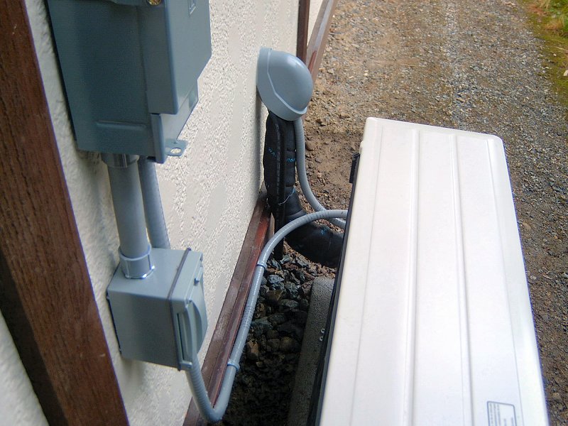