

The Energy Efficient Home

I started thinking about making our living space more energy efficient back when I was in college, when I did some volunteer
work at a place called Urban Options in East Lansing (now called
Michigan Energy Options![]() ).
We only had an apartment in a drafty old Victorian house, but I was still into "green living" well before it was trendy, I guess.
When I later moved to a rental house, I did what I could with caulk, insulation, set-back thermostats and such to try and
reduce our energy costs (and save money of course). Now that we own a home and are renovating everything in the house, I
can finally take some significant steps to improve our homes energy efficiency as I rebuild the entire structure and install
new appliances and mechanical equipment. Back in the college days, there really wasn't a definitive answer to what making
an energy efficient home actually meant - you just did what you could to stop air leaks and use more efficient heating and
cooling practices. Now we've got a much better definition of what an energy efficient home really is.
).
We only had an apartment in a drafty old Victorian house, but I was still into "green living" well before it was trendy, I guess.
When I later moved to a rental house, I did what I could with caulk, insulation, set-back thermostats and such to try and
reduce our energy costs (and save money of course). Now that we own a home and are renovating everything in the house, I
can finally take some significant steps to improve our homes energy efficiency as I rebuild the entire structure and install
new appliances and mechanical equipment. Back in the college days, there really wasn't a definitive answer to what making
an energy efficient home actually meant - you just did what you could to stop air leaks and use more efficient heating and
cooling practices. Now we've got a much better definition of what an energy efficient home really is.
The good news is, "green building" and "energy efficient home" building techniques are very popular these days, so
there's plenty of information available on both subjects, mostly through the Environmental Protection Agency's
Energy Star![]() program web site. Energy Star also has a complete verification list of the specifics to determine if the entire home is
Energy Star qualified, so there's no more guessing about what works and what doesn't.
program web site. Energy Star also has a complete verification list of the specifics to determine if the entire home is
Energy Star qualified, so there's no more guessing about what works and what doesn't.
 At least it's not a negative number.
The bad news is that while I'm taking as many steps as I can to improve our homes efficiency, it's a slow process and the
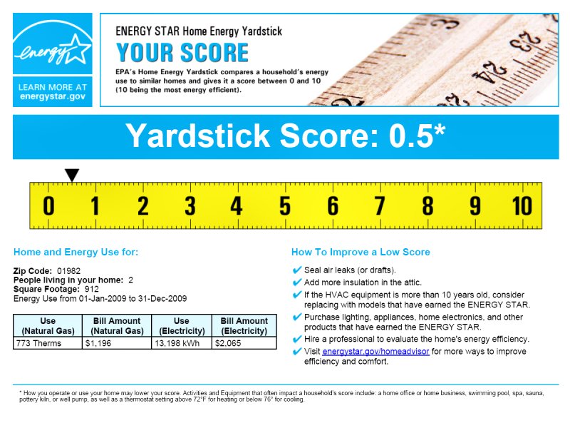
home is performing horribly at the moment. One of the ways to measure our homes energy efficiency is to use the
Energy Star Home Energy Yardstick![]() which provides a rating based on the energy usage data provided and cross-referenced against heating and cooling degree days
for the time period in question. On a scale of 1 to 10 (10 being the best), we scored a whopping .5. Sad, but it
makes sense given that much of our house remains uninsulated while renovations are being completed.
which provides a rating based on the energy usage data provided and cross-referenced against heating and cooling degree days
for the time period in question. On a scale of 1 to 10 (10 being the best), we scored a whopping .5. Sad, but it
makes sense given that much of our house remains uninsulated while renovations are being completed.
Unfortunately, there doesn't appear to be a way to make an existing home an Energy Star qualified home under the current guide lines. Qualification only applies to new construction, so despite the fact that I'm essentially re-building every component of the home, I cannot create a true Energy Star qualified home according to the EPA. Even though I'll never get an "official blue sticker" for my electrical panel, there's still nothing that prevents me from going through all of the Energy Star qualification check lists and doing everything right. Even without the sticker, we can still enjoy the benefits of lower energy costs and reduced environmental impact of an Energy Star qualified home. And I haven't given up on that sticker yet either... I'm working with the EPA and an Energy Star rater to determine if I can still receive the appropriate verifications to qualify for the program even though I'm doing all the work myself.
Reducing energy use costs for our house is the main goal of improving the homes energy efficiency, but that means we must do a lot more than just concentrate on weatherization. In order to enjoy a comfortable living space with a minimal ongoing energy budget, we need to address the entire building as a working system. Weatherization is certainly a big part of improving the energy efficiency of the structure, however the additional factors of Indoor Air Quality (IAQ), building moisture and mold prevention, and combustion safety are no less important. Throughout the renovation project, it's been necessary to ensure these factors have always been in mind while making improvements to the building. A little caulk around the windows and a few rolls of fiberglass insulation in the attic when it's all done isn't going to do the job.
Improving Energy Efficiency
Creating a Thermal Barrier
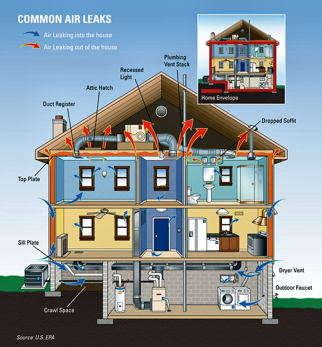
Perhaps one of the most important and cost effective steps in improving heating and cooling efficiency is to prevent
air leaks in to and out of the conditioned space. We're paying to heat (or cool) the air inside the home, and the
greater the temperature difference between in the air inside the building and the air outside the building, the greater
the stack-effect forces driving convective losses through air leaks. The air in the building is warmed by the homes
heating system (radiant floor heat in our case), which then makes the air less dense so it wants to rise. In order for
the light, warm air to rise and escape through air leaks in the attic, cool, dense air tries to enter the structure
through air leaks in the foundation or window and door openings (making the home feel "drafty"). The same thing happens
in reverse when cooling the home, in that warm air is drawn in through the attic to replace cool air that's lost through
the foundations. If the air leaks are stopped, the stack-effect can be minimized.
Fiberglass insulation, which is what we're using the walls and attic, does nothing to stop air movement - insulation prevents conductive heating and cooling loss, not convective interchanges. In order to stop air leaks we created a sealed envelope between the conditioned space inside the building as the first layer of the thermal barrier, followed by the insulation, then another sealed envelope / moisture barrier outside the building, just below the "weather shell", as the outer layer of the thermal barrier.
Sealing Air Leaks
Because we've been gutting each room to the studs to gain access for new wiring and plumbing as we work through the interior
renovation, the process of sealing the interior is relatively straight forward. Once any electrical boxes, wiring and
plumbing is in the wall, the next step is to seal any penetrations in the top and bottom plates of the wall with expanding
spray foam. Rather than use throw-away cans of Great Stuff™, which pretty much need to be emptied once they're started,
I use a Todal Products®
![]() Pur Shooter gun and their
Pur Fill 1G foam for air sealing any large gaps (see the HVAC section regarding
under-floor insulation for more information on the foam gun kit).
Pur Shooter gun and their
Pur Fill 1G foam for air sealing any large gaps (see the HVAC section regarding
under-floor insulation for more information on the foam gun kit).
Once the big penetrations are sealed with foam, I also go around the perimeter of any electrical boxes with the foam gun,
sealing the wiring openings and filling the space between the back of the box and the outer wall sheathing with foam. If the
wall has a window in it, I then seal the small gap between the window and the rough opening framing with
DAPTex
![]() No-Warp®
Window & Door Sealant. While DAPTex is in an aerosol can, the nozzle can be removed and cleaned with soap and water between uses
so the stuff has a good shelf life. It also doesn't expand like crazy the way polyurethane foam does, so there's no possibility
of distorting the window or door casing after it expands.
No-Warp®
Window & Door Sealant. While DAPTex is in an aerosol can, the nozzle can be removed and cleaned with soap and water between uses
so the stuff has a good shelf life. It also doesn't expand like crazy the way polyurethane foam does, so there's no possibility
of distorting the window or door casing after it expands.
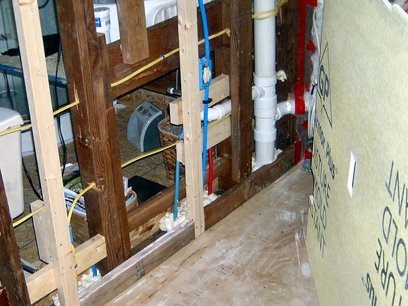 Sealing plumbing and wiring.
Next the wall cavities are filled with unfaced fiberglass insulation (see below), then the entire surface is covered with
4-mil polyethylene plastic sheeting as a vapor barrier. Before installing the poly, I go around the perimeter of the wall
(top plate, bottom plate, corner studs, window openings and electrical boxes) with a nice heavy bead of
Tremco®![]() Acoustical Sealant, which is a non-hardening, non-skinning synthetic rubber caulk. The stuff is the nastiest, stickiest mess
to ever come out of a caulk gun, but it works. I used "regular" acrylic latex caulk to seal the perimeter of the vapor barrier,
but the stuff usually skinned over before I got the poly in place and didn't stick very well so I ended up using a lot more caulk than
I wanted to in order to get the vapor barrier well sealed to the wall perimeter. The acoustic sealant sticks to the
poly (and everything else) like crazy, so it's perfectly suited to the task and allows plenty of work time since it never
skins over. Once the poly is up with a couple staples to hold it in place, the sheet is smoothed and tightened over the
wall and stapled in place around the perimeter and every 12-inches or so throughout the field.
Acoustical Sealant, which is a non-hardening, non-skinning synthetic rubber caulk. The stuff is the nastiest, stickiest mess
to ever come out of a caulk gun, but it works. I used "regular" acrylic latex caulk to seal the perimeter of the vapor barrier,
but the stuff usually skinned over before I got the poly in place and didn't stick very well so I ended up using a lot more caulk than
I wanted to in order to get the vapor barrier well sealed to the wall perimeter. The acoustic sealant sticks to the
poly (and everything else) like crazy, so it's perfectly suited to the task and allows plenty of work time since it never
skins over. Once the poly is up with a couple staples to hold it in place, the sheet is smoothed and tightened over the
wall and stapled in place around the perimeter and every 12-inches or so throughout the field.
The final step is to "sweat the small stuff" which means going over the entire wall and seal any remaining penetrations and seams in the vapor barrier with tape. I use 3M™ VentureTape™ Polypropylene HouseWrap Sheathing Tape, which is not cheap, but it very sticky and pretty heavy (compared to plain old packing tape) so it works well. This is the very nit-picky step, since I tape every staple used to hold the poly in place, as well as the seams and big stuff. Once it's done, the result is an air tight, moisture proof surface, ready for the final wall covering (GWB, panelling, etc.).
Insulating the House
 Wall insulation and vapor barrier (4 photos).
Insulating the Exterior Walls: 2008 2018? -2024
As discussed above, the wall insulation must be installed before completing the interior vapor barrier. For
most of the wall insulation I chose John Mansville Formaldehyde-free™
Unfaced FiberGlass
![]() R-13 batts (rather than the
pink stuff) to reduce bringing more Formaldehyde into the house. I also like it because it's white, and there's often long delays
between getting the insulation up and sealed before I get around to applying the final wall covering. It sounds silly, but I can stand
looking at white insulation for a while instead of a bunch of pink walls. The JM insulation also comes with a couple Easy-Fit™ batts in
each bundle, which are perforated length-wise for when I need to insulate a non-standard width wall cavity.
R-13 batts (rather than the
pink stuff) to reduce bringing more Formaldehyde into the house. I also like it because it's white, and there's often long delays
between getting the insulation up and sealed before I get around to applying the final wall covering. It sounds silly, but I can stand
looking at white insulation for a while instead of a bunch of pink walls. The JM insulation also comes with a couple Easy-Fit™ batts in
each bundle, which are perforated length-wise for when I need to insulate a non-standard width wall cavity.
Unfortunatly, I can only get an R-13 (3-1/2 inches) value for the walls, since I'm not re-framing the entire house with 2 x 6 studs to create the 5-1/2 inch deep cavity required for the recommended R-19 wall insulation value. I suppose if I'd added an inch of rigid foam to the exterior sheathing before I put up the siding I could have hit R-19, but I'm confident that my over-the-top vapor barrier will allow my insulation to perform at its best, so R-13 should do the job. Time will tell.
Most of the exterior walls were insulated and covered with plastic by 2018, although the walk-in closet/laundry room remained un-insulated until now. After taking care of all the attic floor work and insulation installation (see below), I was finally able to get the closer/laundry room cleared of everything and take care of the last of the wall insulation by mid-Winter 2023-24. I still need to seal the vapor barrier plastic for living room and bedroom exterior walls, but that's underway now. I ended up having to use the pink stuff for the last of the closet/laundry room wall insulation, as it seems the JM stuff mentioned above is only available by special order in bulk quantities. A little leftover R-13 from the attic, along with one more new roll of the stuff and the wall insulation was finished up without issues.
Insulating the Floor: 2003-2009
Because the house has a crawl space, rather than a full basement, some consideration must be given to whether to
treat the crawl space as conditioned space then insulate and seal the foundation and ground, or treat it as
unconditioned space, leaving it ventilated and insulating and sealing the bottom of the floor joists. With radiant
floor heat as our heat source, we had little choice but to insulate at the bottom of the floor joists. We also enjoy
a very high water table here, so the ground in the crawl space is usually quite damp. Trying to make the crawl space an
air-sealed conditioned space would have required installation of an underground drain system with multiple sumps, and
since the house is the lowest point of the property, there's really no where to pump the sumps out to. The final
solution is actually a combination of both schools of thought (seal and conditioned versus vented and unconditioned
crawl space), which I arrived at to balance the need to insulate the radiant heating system as well as deal with the
moisture in the crawl space. For details regarding the insulation under the floor, please see the
HVAC Floor Insulation section, since the insulation system is an
integral part of the heating system. I intend to add rigid board insulation to the crawl space walls, and
already have heavy plastic sheeting on the ground under the hosue to help with moisture control. The crawl space is
vented as well (for moisture), although the vents are closed in the winter.
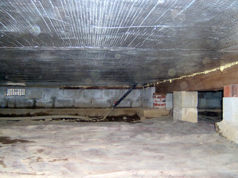 Under floor insulation.
The interior of the floor still requires air sealing regardless of what's going on with the floor joists and
in the crawl space. I don't roll plastic sheeting over all the floors, however the floor still gets a complete
perimeter seal with caulk. Before the walls are covered, any space between the wall vapor barrier and the floor
is filled with that nasty acoustic sealant, then the sub-floor sheathing is applied - either tongue & groove OSB
sub-floor panels (for under the laminate flooring) or cementitious tile backer-board (for under the tile). The OSB
or backer-board then forms a seal across the plane of the floor either with sub-floor adhesive under the OSB, or the
thinset mortar under the backer-board. The finish floor is also sealed around the perimeter of the room when it's installed.
The laminate flooring has a 3mm pre-glued foam backing and is caulked around the entire perimeter with 1/4-inch bead of
acrylic latex caulk before baseboard trim in installed. Tile and grout is held away from the wall with a spacer (a 1/4-inch
thick strip of plywood) during installation, then the remaining gap is also filled with acrylic latex caulk once the
mortar and grout has cured. I use DAP®
Alex Plus®![]() siliconized acrylic latex caulk for all the perimeter floor gaps (and everything else that doesn't get the acoustic sealant,
for that matter).
siliconized acrylic latex caulk for all the perimeter floor gaps (and everything else that doesn't get the acoustic sealant,
for that matter).
Insulating the Attic: 2006-2023?
Heat rises, so lets put lots of insulation in the attic, right? Wrong, mostly… Folks tend to put lots of insulation
in the attic because it's easy to get at, not necessarily because of what's going on up there and how it affects the
conditioned space below. If the interior is properly air-sealed (which ours is), then there's no chance for convective heat loss
or gain through the attic. The problem is there's still an increased chance for conductive heat loss through the
ceiling and framing into the attic, since the ceiling surface and framing are naturally warmer than other surfaces inside
the house (convective heat transfer is how we all heat the house, remember, so that warm air rises in the home). Even
more severe is the chance to reduce interior cooling efficiency in the summer when a super-heated attic conducts heat
into the cooler home. So attic insulation is still a big deal, which is why the EPA recommends around 16 to 18 inches of
insulation (R-49) for attics in our "Zone 5" area.
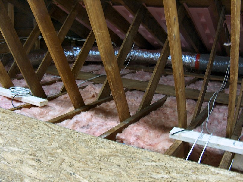
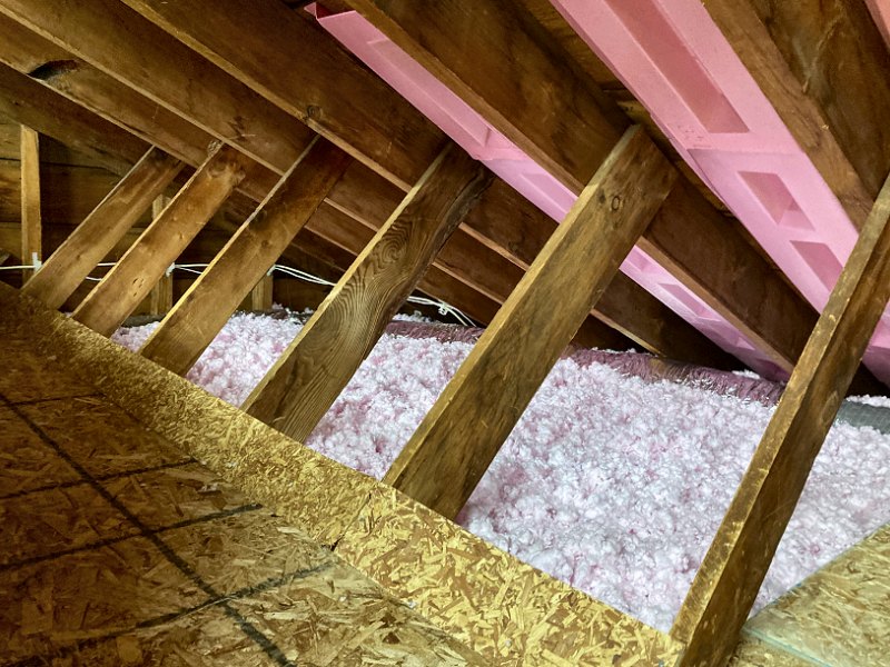
Our ceilings are built with 2 x 6 joists, so the easiest place to start in the attic is with some 5-1/2 inch thick
fiberglass insulation in all the joist bays. I used Owens-Corning®
Pink Fiberglas®![]() R-19 insulation for the first layer of attic insulation. The interior ceiling gets the same vapor barrier / air sealing
treatment as the walls, with a little extra fussy attention paid to the recessed lighting fixtures. Recessed lighting
is a notorious source of air leaks, so I selected ICAT (insulation contact, air-tight) fixtures, then caulked, taped
and foamed even the tiniest openings in the fixtures during installation. The fiberglass insulation is then "fluffed"
and carefully placed into every nook and cranny between the ceiling joists and other framing and fixtures in the attic.
Another area the requires extra care is the area between the wall top plate and the roof. This critical junction contains
a rigid foam vent to allow air flow between the soffit vents and the attic, so the insulation is cut at an angle and
placed between the top plate and the vent shield, as well as in any voids between the shield and the framing members.
Once all little bits are placed around the top plate, the rest of the insulation is easily rolled out between the joists. Getting the
new attic insulation installed has been an ongoing project for many years. The first new stuff went in when the bedroom was enlarged back in
2006 (but only over the new section, not the entire bedroom), and then the offices / boiler room / genkan area
was fully insulated as it was put together in 2006 as well (with 5-1/2 inches above the perimeter, and closer to 1-foot of stuff near
the peak). The rest of the house has had no attic insulation since we had our first dumpster here for the roof work back in 2006 (and tossed
out all the old insulation through the 3-foot vent hole in the gable end). When we finally got the old living room ceiling out in 2017, we just
stapled up some plastic sheeting to keep the wind out, but still no attic insulation for most of the house. Sad.
R-19 insulation for the first layer of attic insulation. The interior ceiling gets the same vapor barrier / air sealing
treatment as the walls, with a little extra fussy attention paid to the recessed lighting fixtures. Recessed lighting
is a notorious source of air leaks, so I selected ICAT (insulation contact, air-tight) fixtures, then caulked, taped
and foamed even the tiniest openings in the fixtures during installation. The fiberglass insulation is then "fluffed"
and carefully placed into every nook and cranny between the ceiling joists and other framing and fixtures in the attic.
Another area the requires extra care is the area between the wall top plate and the roof. This critical junction contains
a rigid foam vent to allow air flow between the soffit vents and the attic, so the insulation is cut at an angle and
placed between the top plate and the vent shield, as well as in any voids between the shield and the framing members.
Once all little bits are placed around the top plate, the rest of the insulation is easily rolled out between the joists. Getting the
new attic insulation installed has been an ongoing project for many years. The first new stuff went in when the bedroom was enlarged back in
2006 (but only over the new section, not the entire bedroom), and then the offices / boiler room / genkan area
was fully insulated as it was put together in 2006 as well (with 5-1/2 inches above the perimeter, and closer to 1-foot of stuff near
the peak). The rest of the house has had no attic insulation since we had our first dumpster here for the roof work back in 2006 (and tossed
out all the old insulation through the 3-foot vent hole in the gable end). When we finally got the old living room ceiling out in 2017, we just
stapled up some plastic sheeting to keep the wind out, but still no attic insulation for most of the house. Sad.
 Proper attic insulation work begins at last.
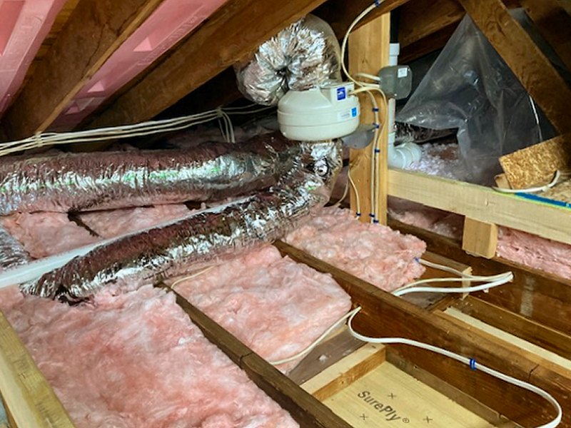
With work finally underway on the house interior again in late 2022 (see the Living Room page in the Interior section), I would be able to once more make some progress on insulating the attic — once I finished all the rough carpentry to get the living room ceiling level. That work was completed in late Winter 2022-23, and after I got the new recessed lights installed and a couple in-ceiling speaker locations worked out, I got up a new vapor barrier, and rolled out a new layer of R-19 unfaced insulation over the entire living room. This is where things in the attic start to get a little complicated…
The next attic insulation step is to add another 10 inches or so (R-30 unfaced fiberglass) of insulation above the new layer of R-19
in the joist bays. The "normal" method of doing this is to just unroll R-30 stuff over the entire attic, perpendicular to the
joists, and the job is done with the recommended R-49 insulation thickness. That's a fine idea for attics that are completely open and have no floor.
Our attic is certainly not that — half the space has the "sorta truss" boards between the roof rafters and the ceiling joists,
there's HRV duct work all around the perimeter, and the area over the bedroom, bathroom, and closet has a floor nailed to the tops of the ceiling joists
that is covered with bins and boxes of stuff. We feel we need to keep the ability to have attic storage available, which means we're going to need to
keep an attic floor. If we want to achieve that R-49 insulation level in the attic, we determined the only viable solution would be to raise the attic
floor, then fill the area beneath the floor (and around the perimeter where there is no floor) with blown-in fiberglass insulation, using the
Owens-Corning®
AttiCat®![]() insulation system. Rather than attempt to roll out additional fiberglass batts over the top of the joists and trim them to fit everything, the
blown-in material will do a superior job of filling any existing voids around the framing members, as well as fill any space around the ventilation ductwork.
We'll likely still use a few rolls of the unfaced R-30 stuff for the easier to get at areas (and then fill in any gaps with the shredded
stuff from the AttiCat® blower). An additional advantage of the AttiCat®
system is that the fiberglass will expand as it's installed, rather than slowly settle like blown-in cellulose insulation. That all sounds
good, but that means I need to re-arrange everything in the attic (or bring it all back down, and we have no where to put it), then
remove the old flooring, build support for a new floor, then insulate the space and install the new floor. No problem!
insulation system. Rather than attempt to roll out additional fiberglass batts over the top of the joists and trim them to fit everything, the
blown-in material will do a superior job of filling any existing voids around the framing members, as well as fill any space around the ventilation ductwork.
We'll likely still use a few rolls of the unfaced R-30 stuff for the easier to get at areas (and then fill in any gaps with the shredded
stuff from the AttiCat® blower). An additional advantage of the AttiCat®
system is that the fiberglass will expand as it's installed, rather than slowly settle like blown-in cellulose insulation. That all sounds
good, but that means I need to re-arrange everything in the attic (or bring it all back down, and we have no where to put it), then
remove the old flooring, build support for a new floor, then insulate the space and install the new floor. No problem!
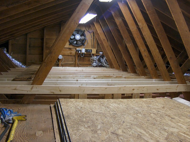
Raising the Living Room & Kitchen Attic Floor: Early Spring 2023
As mentioned above, I had decided to raise the attic floor in order to maintain storage ability in the space while getting to that R-49 insulation
goal. With the bottoms of the ceiling joists for the living room level, I could now figure out how much I needed to raise the attic floor. Starting
in the center of the attic at the East end (where the ceiling joist had the smallest thickness of lumber added to the bottom), I measured
up a total of 16-inches to get the new attic floor height (R-19 at 5-1/2" plus R-30 at 10-1/4" comes to R-49 at 15-3/4",
rounded up to an even 16"). More fun with the 6-foot level, an 8-foot 2x4, and a couple clamps and it worked out that I could use a 10-foot 2x4
as the new floor support, which would give me enough length to attach the 2x4 to the truss board at each end, with a few short 2x4 chunks attached vertically
between the top of the ceiling joist and the bottom of the 2x4 along the middle. That would give me a new floor section a little over 5-feet wide
in the middle, along with about 2-foot wide sections between the truss boards on each side.
 The re-built attic floor and first insulation layer (3 photos).
To build the new attic floor I had to get rid of part of the old attic floor, and also get all the stored stuff out of the way. That work had started not long after we removed the flooring underlayment back in late 2021 (see the Bedroom page in the Interior section for more info), which also provided the opportunity to get a bunch of 7/16" OSB sheets loaded into the attic. At that time I managed to remove most of the old attic floorboards over the living room, after moving around the storage boxes and bins, and then stack the eight sheets of OSB on the joists over the living room. The next big supply run in early 2023 (the Vanagon is still out of commission, so I'm at the mercy of a friend with a pick-up truck for Home Depot runs) included 30 2x4s to use for the new living room fusuma door header, tokonoma framing, and then the remaining 20 or so for use in the attic.
When all the rough carpentry for the living room was taken care of, I then turned my attention to making some progress on that attic floor. All the 2x4s were
eight feet long, even though I'd determined the new attic floor supports need to be ten feet long (the 8-foot pieces were a lot easier to get into the attic
than 10-footers would have been). To get the 10-footers I'd need and to get the little floor support pieces installed, I planned to use
a Kreg Jig® HD
![]() which I picked up a while ago
(and is now discontinued, unfortunately). This thing is built specifically to join 2x stock using pocket screws, so it would work to
lengthen the 8-foot pieces to 10-foot pieces, as well as provide a secure method to add each floor support piece to the tops of the ceiling joists.
which I picked up a while ago
(and is now discontinued, unfortunately). This thing is built specifically to join 2x stock using pocket screws, so it would work to
lengthen the 8-foot pieces to 10-foot pieces, as well as provide a secure method to add each floor support piece to the tops of the ceiling joists.
The new attic floor construction work began by end-joining a 2-foot 2x4 piece to one of the 8-footers with a pocket screw and construction adhesive, then gluing and screwing that 10-foot piece to the gable studs at the end of the attic. I centered the 10-foot length under the roof peak, and leveled it at the 16-inch height above the bottom of the ceiling joist. I then set up the laser level at the other end of the attic with a vertical line cast along the center of the roof and the gable end, and the horizontal line level with the top of the new floor support. That allowed me to work along fairly quickly on each new floor support piece — I'd start installing each support by marking the center line on the 8-footer (5-feet from one end), then clamp it to the truss boards with the top touching the horizontal level line. I could then measure the length for the three support blocks between the 2x4 and the ceiling joist. Next I'd head to the shop and cut the support chunks, then drill a pocket hole in one end. Back to the attic and each block was glued and screwed into place on the ceiling joist, then the 8-footer got a 2-foot piece glued and screwed to the end and that 10-foot piece was then glued and screwed to the support blocks and the truss boards (the two nearest the boiler room actually got a 4-foot piece added to each, to provide a little area to get at the HRV dampers over the boiler room). After a few days of this I had all the new floor supports in place for half the house, and could now get back to adding more insulation and getting the new OSB floor installed — which would allow us to re-arrange all the boxes and bins again, then work on raising the rest of the attic floor and insulating the remainder of the attic.
 The second layer of attic insulation (4 photos).
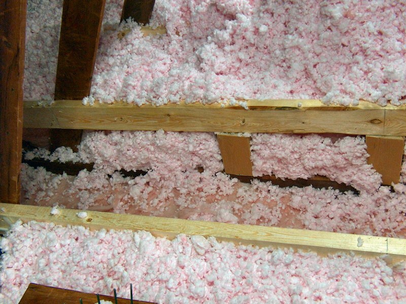
More Attic Insulation & Half a New Attic Floor: Spring 2023
Before screwing down the new OSB for the newly raised half of the attic floor, I needed to get all the insulation in place that the floor would cover (and make
inaccessible). As said above, the plan for the insulation under the attic floor was to get that R-19 layer down between the joists (which was done),
then get another layer of R-30 down between the new floor supports and fill in all the gaps with the shredded fiberglass stuff from the AttiCat®.
The problem was that the rest of the attic was still packed with boxes and bins, so there was no way I was going to rent that AttiCat® machine
and try to blow in half the attic with all that stuff up there. I decided the best way to proceed would be to just attempt to shred a couple bales of the
AttiCat® material by hand, then blow it into place as I worked along each bay installing the R-30 layer on top of the R-19 stuff.
To shred the stuff I grabbed my Lee Valley "hand rakes" from the garden shed and used those to break up the stuff from the insulation bales and spread it
around a bit. I also picked up a little 3-hp, 3-gallon shop vac from Harbor Freight that also had an outlet to use as a blower (an electric leaf blower was way
too powerful, but this thing was just right). Hand shredding worked pretty well, but it was a lot of work — I don't think I'll be doing that again if I can
manage it for the other half of the attic.
Once the entire area for the new floor was well filled with insulation, I then started getting the new OSB flooring in place for half the attic. I started with a full 4 x 8 sheet at the far end, screwed to the new floor supports every 8-inches or so with 1-1/4" square drive screws. I didn't use any sub-floor adhesive on the big sheets, in case someone ever needs to remove this stuff in the future (to get at the wiring or light fixtures for some reason). I then measured and cut the smaller strips of OSB in the shop, and screwed those down next to the full sheets to take care of the center section flooring. These pieces went in with lots of fuss, as none of the truss boards were actually in line with each other. I basically cut a strip that was a little wider than needed, then had to mark and cut a little slot to fit around each truss board to get the piece to lay flat. That also meant I had to add a load of little scraps of 2x2 to the truss boards to support the new floor in between those boards and ensure the new floor was well supported.
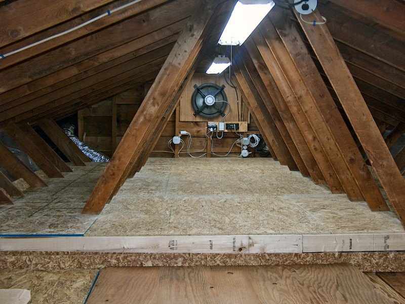 The first half of the new attic floor is done (5 photos).
For the roughly 2-foot wide sections on each side, I again cut some stock in the shop then laid the piece in place and marked where material needed to be removed for the truss boards (I didn't want to cut up any of the full 4x8 sheets that were already in the attic so I can use those for the other half of the new floor when the time comes). I used the jig saw in the attic to cut the little clearance slots for the truss boards, and eventually got the side strips screwed in place. The last step was to then go over the entire new floor area and fill in all the remaining little spaces between the truss boards and along the end between the gable studs with little pieces of OSB and more 2x2 supports as needed. I basically wanted to ensure there are no little gaps anywhere where something could fall between the floor boards and disappear forever in the insulation below. I then filled any remaining little cracks or spaces with construction adhesive, and with that the first half of the raised attic floor work was completed. Before I filled the new area with boxes and bins, I also added some 1/4-inch OSB strips along the outside edges of the new floor to prevent anything from rolling off the edge, and added some plastic sheeting to the truss boards so the new floor won't get covered with blown in insulation when we eventually get the machine to complete the attic insulation project.
The other half of the attic (over the bedroom and closet) will probably have to wait until Fall for more work, as it's starting to get pretty warm up there on sunny days and it's just too uncomfortable to try and work in that heat. I also need to get the old bedroom ceiling removed and then work out the framing for the new attic entry door. With that work taken care of (details are on the Bedroom page), the attic is now ready for "round 2".
 An attic tool (4 photos)?
Bedroom & Closet Attic Work: Fall 2023
The attic over the bedroom and closet/laundry room will get the same treatment as the space over the living room and kitchen: First, any ceiling
fixtures and other wiring holes will need to be air sealed with the foam gun, then a layer of R-19 fiberglass will go down between the ceiling joists. Next
the floor supports for the raised attic floor will get built, then some AttiCat® loose fill will need to be spread to
fill any gaps between the framing and the R-19. That should then get covered by some R-30 between the new floor supports, and finally the OSB for the
raised floor can go down for the remainder of the attic.
That all means I'll need a couple more shredded bales of that AttiCat® loose fill stuff available, and I'm not looking forward to shredding the stuff by hand again. Years ago when I was working on the Bamboo Containment dilemma, a friend gave me some goofy, sorta roto-tiller thing called a Garden Maid® Soil Blender® (he had picked up a pair of the things for cheap at a yard sale, and didn't need two of them). He thought it might help to stick in the ground and gather up Bamboo roots (it didn't), so I thanked him and just tossed it in my storage locker. Thinking about the need to shred at least two more bales of insulation by hand (and probably another four or five bales for the rest of the attic), I remembered this thing in storage and decided to try and build myself my own AttiCat® insulation shredder…
I started by dis-assembling the unit to just get it down to the motor and blades. With the wheels and handle bar removed, it worked out that mounting it in a plywood box with the wheel mounts in a wood block at each side and a support to hold the blade tubes would hold the thing well enough. I had a bunch of old attic floor pieces of 2x4-foot and 4x4-foot 5/8" plywood that I used to fabricate the box for the motor and blades unit, then used up more of the old plywood to create a feed hopper that would allow a half-bale of insulation to feed into the top of the blade box. I replaced the variable speed handle bar switch with a simple on/off switch mounted to the box, and the thing was ready for the attic. I then set about getting all the new electrical boxes and recessed lights sealed with the foam gun, then the first roll of R-19 went down over the bathroom and the outside wall end of the closet/laundry room ceiling. I'd need to get some of the raised attic floor support framing work done before I could really try out the new shredder, so that work happened next.
Raising the Bedroom & Closet/Laundry Room Attic Floor: Fall 2023
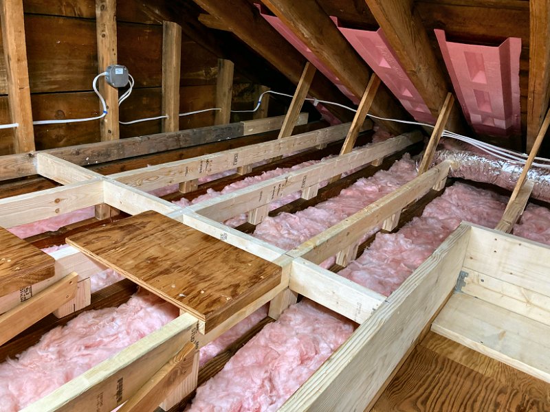
To get the new raised floor supports installed for this section of the attic I tried a little different approach than I'd done over the living room
ceiling, and it seemed to work pretty well — rather than clamp the long 2x4s in place then measure the required support pieces between the
ceiling joist and the new 2x4 (which I couldn't do, since there's no truss web boards available for clamping the 2x4s), this time I mounted the
laser level to the hatch framing, shot a level line even with the existing raised floor, then simply measured from the top of the ceiling joist to
the laser line to get all the support piece lengths. This also allowed me to get many more of the support pieces cut at a time, as I could measure
everything for two or three joists for each trip to the shop, rather than being limited by having to work to a single, clamped-in-place 2x4.
 Work on the rest of the attic is underway (11 photos).
Another change to the attic floor framing for this half of the attic compared to the living room framing was the addition of some extra truss webs between the original ceiling joists and the raised floor supports. The living room ceiling span had been originally built with "Fink" style truss webs between the rafters and ceiling joists, since there were no bearing walls below that 26-foot span. The bedroom ceiling area had no truss webs and relied on the closet and bathroom bearing walls for support, although those still left about a 16-foot un-supported span over the bedroom. When planning the bedroom/closet wall re-builds I had added a few truss webs between the rafters and the joists at the ends of the ceiling joist spans, along with a couple "King" truss webs from the rafters to the joists that were cut for the new attic hatch (see the plans available on the Bedroom page), and then added a long web to make a "pseudo ladder" style floor truss for those cut ceiling joists. Now that I was actually working on the floor supports, I decided a better approach would be to add "Pratt" style truss webs between all the raised floor supports and ceiling joists for this half of the attic. This should add plenty of support to this half of the new attic floor, while leaving the space above the new floor open for storage. I also found that the new "Pratt truss" ladder trusses were a little "wobbly" on the longer sections, meaning there was some side-to-side deflection apparent as I crawled around on the raised sections to work on the remaining joists. This movement will go away when the 7/16" OSB flooring gets screwed down, but that won't happen until all the new insulation is in place. To make things a little more rigid while working, I added cross-members between the raised floor support's top 2x4 (the top "chord" of the new ladder truss) at the new floor centerline on one side of the hatch, then offset from the centerline by 4-feet on each side of the centerline across the rest of the attic. These cross-members eliminated all the side-to-side deflection, and will also support the seams of the new flooring sheets when those go down after the insulation work is finished.
More Attic Insulation Work: Fall 2023
It's finally happening — the rest of the attic is getting new insulation, somthing it hasn't had since 2006! With all the raised floor support
work taken care of, I was able to install another four rolls of R-19 unfaced fiberglass over the second half of the attic. That got everything over
the remainder of the attic space covered with the "first layer" of insulation, but I still want to add another layer to get that R-value up.
 Attic insulation work for the rest of the attic (7 photos).
The living room and kitchen attic had plenty of space available between the leveled ceiling joist bottoms and the raised attic floor to get 16+ inches of insulation in there and hit my R-49 goal (using a value of R-3.1 per inch for fiberglass). The bedroom and bathroom ceiling didn't need to be lowered as much as the living room to level them off, and since I'm keeping the new attic floor at all the same level, it's looking like these spaces will get in the R-40 to R-45 range. The closet/laundry room attic got the least amount of ceiling joist work for leveling, so that space will likely end up in the R-30 to R-36 neighborhood. Still, the end result will be much better than what we started with (which was very old, moisture compressed, R-13 stuff from the '70s), and up until earlier this year the living room, bedroom, bathroom, and closet hadn't had any attic insulation for seventeen years.
Anyway, getting the first layer down was simple enough. I'd just get a rough length measuerment for each joist bay, cut an appropriate piece off a roll, then roll it out in the joist bay and fluff it up a bit as I went along. I also made myself a couple work platforms (seen in the first photo to the left) from some old plywood and a couple wood strips to keep them in place on top of the raised floor supports, since trying to balance myself on top of those 2x4s was gettin' old. Once I got the first layer down, I then pulled out the "piggy" to see if the thing will actually do the job to shred the AttiCat® loose-fill stuff. The first problem I ran in to was that there's really not enough space in the attic to stick a half a bale of insulation into the feed hopper. Not so bad… I'd just break off big chunks of the compressed stuff and toss 'em in the hopper. That worked well enough for a little while, but then the thing just stopped feeding anything out the mouth. It turned out the problem was that the compressed stuff was expanding inside the hopper before it would reach the blades, and then just get stuck in place while the blades spun below the insulation and couldn't pull anything down. If I tried to push it down with the tamper, it merely compressed the stuff and it still wouldn't shred. I ended up pulling the hopper off the top and removing half of what was in there, then I put the hopper back in place and tried it again. That worked much better, and as long as I didn't put too much compressed stuff in the hopper at a time and kept stirring it around a bit with the tamper, it would shred the stuff fairly well and spit it out the mouth.
After shredding about a third of the first bale of insulation, I grabbed handfuls of the stuff and spread it around into the gaps between the floor supports. I then added the "second layer" of unfaced fiberglass with two more rolls of R-19 going over the closet/laundry room, the bathroom, and between the floor supports near the hatch. The rest of the bedroom attic then got two more rolls of R-30 added, with a couple extra bits unrolled in the area between the living attic floor and the front and back perimeter walls. I'll likely get one more roll of R-30 to add more to those two areas on each side of the living room attic (since it'll be a lot simpler to just unroll the stuff over those ceiling joists than it will be to fill that whole space with loosfill), and I'll also need a bit of R-30 to insulate the new attic hatch when I get around to building that thing. I then shredded the rest of the bale of loosefill, and used the blower to make a big pile of the stuff in the center of the bedroom attic to get distributed as I put down the new floor. I figure I'll need another two or three bales of loosefill, combined with that extra roll of R-30, to finish filling each side of the living room attic space. For now, I'm satisfied with the state of the attic insulation for this half of the attic, and it's time to get the rest of the attic floor installed — so we can get all the bins of stuff back up there and out of the living room and bedroom!
 The simple layout for the attic floor (1 sheet).
The Remainder of the New Attic Flooring: Late Fall 2023
With the space within the attic floor supports over the second half of the attic well filled with fresh insulation, I could start working
through my stack of 7/16" OSB that I'd been sliding around the attic since March of this year. Once I'd gotten the new hatch opening
framed (discussed over on the Bedroom page), I actually pulled three of the four sheets
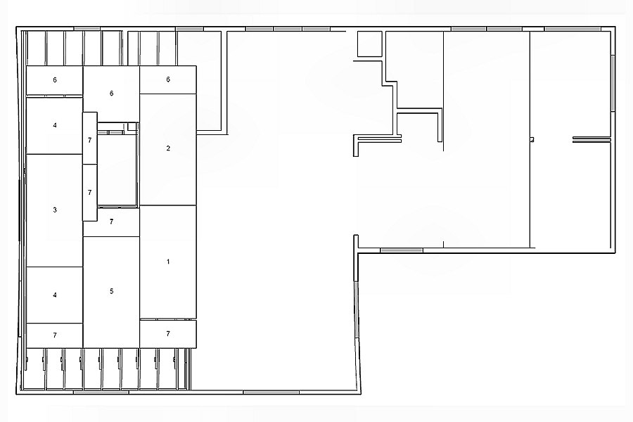
of OSB out of the attic as I was tired of moving it around while working on the raised floor. I then made a basic layout of how the sheets would
get arranged for the new floor so I could pick up any additional sheets I'd need during my most recent supply run. Now I could start working
through the stuff to get the new floor installed.
The first sheet went down between the hatch opening and the gable end wall, followed by a half sheet at each end of that to take care of most of the gable end wall section (these are numbered as 3 & 4 in the plan, but it doesn't really matter in what order they're actually installed). As I'd done for the living room attic floor, the sheets are screwed down with 1-1/4" screws every 8-inches or so, but I don't use any adhesive so they can be removed someday if someone needs access to the wiring in the ceiling. Next, the small piece at the end of the hatch opening was fitted around the "King truss" webs, then another small piece was added between the side of the hatch opening and the existing full sized sheet. The first day of floor work was wrapped up with another small piece at the front end of the gable wall half sheet (these are all pieces of sheet 7, according to the layout plan).
 The new attic floor for the rest of the house (19 photos).
I then put down the nearly full-size sheets to cover the area between the hatch and the front of the house (sheet 5 from the plan), and then the last couple along the edge of the existing floor from earlier this year (sheets 1 & 2 from the plan). Installation slowed a bit after the big sheets went down, as I now had to deal with fitting all the small bits around the truss webs and gable end wall framing. I suppose I could have skipped this, but as I had done on the first half of the floor, I didn't want to leave any openings anywhere where stuff could slip off the floor and be lost in the insulation below forever.
The "fussy" work began along the gable end wall with some blocking added to the wall sheathing, then small pieces of OSB added to fill in the gaps. I even cut little scraps to fit into the gaps along the edges of the studs where they met the floor framing. Once the gable end wall was taken care of, I then worked along the back section above the closet/laundry room, filling in the areas between the truss webs. Next the area behind the hatch and above the bathroom was covered over (which used up sheet 6 from the plan), then I turned my attention the front section over the bedroom. This section was "extra fussy", since I had lots of new truss webs to work around, as well as the old front porch wall section to cover over. Between the careful measuring required for each piece and only being able to cut one piece at a time (since each new piece's measurements needed the previous piece installed), this took quite a while to get all these little bits filled in. After a couple weeks of fiddlin' with little bits of OSB, I had all the raised floor framing covered with new floor (and most of sheet 7 was finally gone). The last task was to then go over all the little seams and gaps with construction adhesive as caulk to fill in those spaces, then I gave everything a quick pass with a 60-grit belt on the sander to remove any bumps between one piece and the next.
It worked out that I had a couple extra 2x4s and about a half-sheet of OSB left (from sheet 7), so I added an extra raised floor section behind a few of the old truss webs along the front section that weren't too tough to get at (pretty much above the tokonoma in the living room). It provides an area to store flat stuff without difficulty, and it used up the last bits of OSB. With that, all rough carpentry work for the interior is done! The new raised attic floor is finished (which I still can't quite believe), and now I just need to take care of the last of the attic insulation work so we can get all the storage bins and boxes put away for the last time.
The Last of the Attic Insulation: Early Winter 2023-24
After I finished the final bits of raised floor work between Christmas and New Years, I was then able to start on the second layer of insulation
for the perimeter of the living room & kitchen attic. I had rolled out one 16-inch wide strip of unfaced R-30 on each side right next to the new floor,
but the plan was to then fill the rest of the space with AttiCat® loose fill stuff that I used the "piggy"
to shred.
 The attic insulation work is done (9 photos)!
I worked through about a quarter of a bale of the stuff for the front of the attic when a few problems appeared. First, the feed chute for the "piggy" was too tall and prevented me using the thing anywhere other than the center of the attic — not terribly difficult to take care of with a quick trip to the shed, and a few minutes later I'd sawed off about 5-inches of the top. Next, I noticed the thing was occasionally slowing down after running for more than 10 minutes, and eventually it stopped working. I removed a few pieces of the plywood casing so I could see the motor and found if I tapped the motor with a hammer it would spin again, but not for long. There was also an impressive arc visible around the commutator at one of the brush holders, so I was thinking the thing may need new brushes. Once I got the end cap off the motor and could get at the brushes, I found they appeared to still have plenty of Carbon available (around 3/8" at least), but one of the brushes seemed to stick in the Brass brush holder a little and wasn't making good contact with the commutator. I few passes on some 320 grit wet sandpaper for that brush and it no longer jammed in the brush holder so the thing went back together. It started right up and ran fine with no more arcing around the commutator. I was back in business.
The final change to the work flow was to pretty much abandon the use of the blower to get the shredded loosefill stuff where I wanted it. The blower had worked well enough to get the material into the small spaces where the rafters meet the ceiling joists, but it pretty much only got about half of a heap of stuff into position, with the other half getting blasted all over the rest of the attic. The blower concept works fine when it's actually carrying the loosefill along within the air stream (which is how the actual AttiCat® machine functions), but for moving a pile of shredded material it just blows it all out of the air stream which makes a huge mess. I had my Lee Valley hand rakes up there already to manually shred any large chunks that made it through the "piggy", and found those also worked very well to scoop up the shredded loosefill and spread it around.
So, to get through the last couple bales of stuff, I'd get about a quarter of a bale shredded into a big pile on a sheet of plastic, then scoop into a plastic bag and drag it over to the edge of the floor where it was going to be spread out. I'd then dump out the bag of material over the final area, and finish spreading it out (and fluffing it up a bit) with a couple small leaf rakes from the garden shed. This worked really well (and didn't make a huge mess). After a few days of this process the rest of the attic was fully insulated at long last.
Moisture & Indoor Air Quality
Dealing with Moisture
With a totally air-sealed, conditioned space inside the home and piles of lofty fiberglass insulation in the walls and
ceiling to prevent conductive heat transfer, we're faced with an additional problem of moisture in the walls and attic,
which can lead to mold... that's bad. Some moisture in the wall and ceiling insulation is inevitable, since there's always
some interchange of warm and cool air within the insulation layer. Condensation appears whenever warm, moist air meets
cooler air that cannot hold as much moisture. In order to prevent that condensation from causing problems, the insulation
materials should not absorb moisture (fiberglass cannot absorb moisture), and the moisture vapor needs to be removed
from the insulation layer. If we encase both sides of the insulation layer in plastic sheeting, any moisture that's
within the cavity will be trapped - this is where house wrap comes to the rescue. House wrap is a thin sheet of flashspun
high-density polyethylene fibers that keep air and bulk water out of the wall, but allow moisture vapor to escape
through microscopic pores in the material. The key to successful application of house wrap is understanding the
difference between "bulk water" and "moisture vapor".
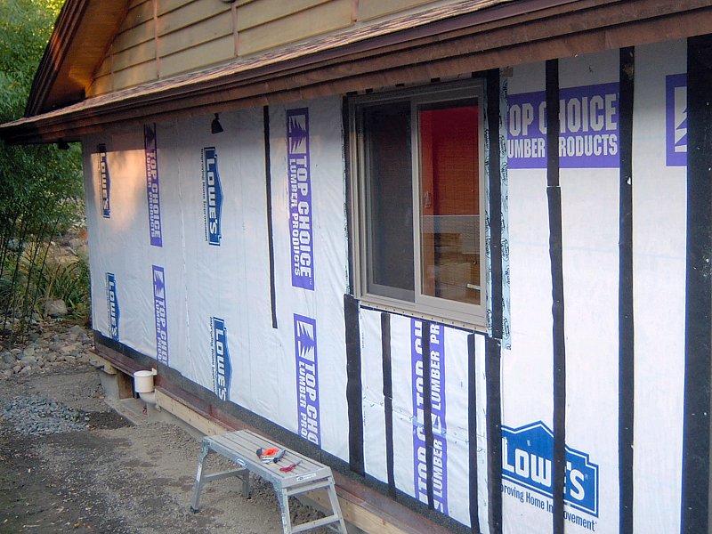 House wrap on the West side.
House wrap is used to create the exterior layer of the thermal barrier, but it is not the "weather shell" for the building - that consists of the roof and siding materials. In order for house wrap to be effective, it needs to be applied to the building just as carefully as when creating the interior vapor barrier. All seams and penetrations in the material must be sealed with tape and/or caulk in order to prevent air infiltration into the insulation layer. When installing the final finish siding to the building, an additional step is taken to assist with moisture control which is to create a minute air gap between the siding and the house wrap to allow some air flow across the house wrap. This is accomplished by simply adding strips of building felt along the vertical surfaces of all wall framing members before attaching the siding. The top plate and bottom plate of the wall do not get the felt strips, since there has to be a way to get air behind the siding. When the siding is installed, all penetrations and vertical seams are caulked, however the top and bottom edges are left unsealed. The siding and roof overhang prevent bulk water from reaching the house wrap, but because of the small air gap, and moisture in the wall still has a method of escape.
The attic presents a different set of circumstances with regard to ventilation and moisture due to the amount of space between the weather shell (the roof) and the insulation layer (the ceiling) as well as the extreme temperature differentials that occur in the attic. The most practical solution to create a "cold attic" by ventilating the attic with outside air all year. When the attic is super-heated by the Summer sun the warm, moist air within will diffuse moisture vapor into cooler insulation layer at an alarming rate. Fresh air is brought into the attic through soffit and gable vents, and attic air is allowed to escape through a continuous ridge vent which alleviates the super-heating issue. In the Winter, any warm, moisture laden air that makes it into the insulation layer (although that shouldn't really occur with a proper vapor barrier) will be removed from the attic through the same fresh air ventilation system.
Indoor Air Quality
Once the thermal barrier is in place and the house good and tight, we're faced with a new set of problems with regard to
indoor air quality and combustion safety. We use a Heat Recovery Ventilator (HRV) to supply fresh air inside the house
without compromising our overall energy efficiency. The HRV also ensures combustion air for the gas stove is readily
available, as well as to remove combustion pollutants produced by the stove. Combustion air and gases are self contained
for the boiler, which employs a direct-vent sealed combustion system. Indoor Air Quality and HRV installation is fully
addressed in the HVAC Ventilation section.
Additional Home Energy Improvments
Energy Efficient Lighting
Wherever possible, we install Energy Star lighting fixtures and make use of Compact Fluorescent (CFL) bulbs. Of course,
the most used lights in the home are the kitchen overhead lights and bathroom vanity lights, and those are unfortunately
using standard incandescent (Halogen) bulbs. The fixtures are Energy Star rated, but for recessed task lighting and seeing
your face at 6 am, the current crop of CFLs just don't cut it. We've tried CFLs for the vanity, but they're not
bright enough (the fixtures use candelabra-base bulbs, and there's still very few options available for a bulb that
will actually fit in there). As for the task lighting in the kitchen, that's currently running PAR20, 50w Halogen bulbs.
Other recessed lighting also uses Halogen bulbs, but we generally dim those fixtures by 50% or more, so I can live with that.
The dimmable recessed lights in the bathroom do make use of R30 CFLs, and while the dimming performance isn't as nice as incandescent,
they function well enough (and provide a better color temperature than incandescent). All other lighting in the house makes use
of either cold cathode fluorescent bulbs, compact fluorescent bulbs, or standard bi-pin fluorescent bulbs.
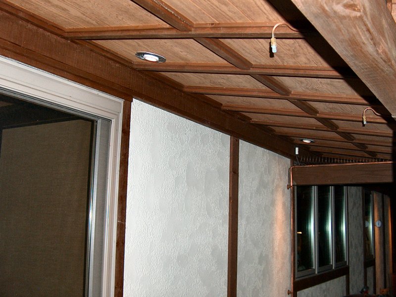 The first attempt with LEDs in the engawa.
LED Lighting Update: Fall 2021
It's been over ten years since I wrote the above section regarding "efficient lighting", and much has changed since then:
Most significantly has been the impressive improvements in LED bulbs, as well as the significant drop in cost of LED bulbs. We've been
steadily upgrading many of the bulbs from CFL to LED (especially as the cost of a replacement Halogen bulb for the recessed
lights is nearly twice the cost of the same bulb as an LED). Even with new LEDs however, the dimming performance and color temperature
of some of the LEDs we tried was awful. Dimming performance has finally been resolved as we migrate the old switches and dimmers to
new Lutron® Caséta® "smart" dimmers and switches (see the
wiring page for details), but the various LEDs we tried just didn't have the nice
"warm glow" of a dimmed Halogen bulb. As energy costs continue to climb, and as we get closer to making progress on the living
room ceiling project (which will add another nine or ten 6-inch recessed fixtures to the mix), I was determined to get the
light output from new LEDs lookin' good.
The first lights I started tinkerin' with were the nine outdoor perimeter "downlights" and the six 4-inch recessed fixtures above the engawa. All these lights are on the same dimmer circuit, and we usually have them on every night, dimmed quite low to give the house exterior a nice illuminated effect. The downlights are floodlight fixtures with a G-8 Bi-pin T4 75w Halogen bulb, while the 4-inch cans have a 50w PAR20 Halogen spot bulb. As the downlights started to finally burn out, I was able to find a proper replacement bulb with a 120v, 3w LED with a "warm white" color temperature of 3,000K. These bulbs look very good in the downlights and have no issues when dimmed (and I also found a similar "mini T-4 JCD" replacement LED for the Halogen under-cabinet lights in the kitchen, at 2,700K). The 4-inch recessed lights required a little more work to get right…
I started by replacing the 50w Halogen PAR20 with a 7w GE® LED PAR20 bulb at 2,700K. The color was good and dimming performance was fine, but the bulb stuck out of the fixture about half an inch (the engawa fixtures are "shallow" cans, as there's only 2x4s for rafters in that roof). Knowing I was going to be adding a bunch of new cans elsewhere in the house, I decided to give a "ceiling light retrofit kit" a try. These kits replace the bulb in the recessed fixture with a new trim and lens unit that has an LED built in to the thing behind the lens, and a bulb socket adaptor and plug for power. They run about $10 or $15 each, so basically the same as a decent LED bulb. I also liked the idea of have a sealed surface for these outdoor cans to keep the bugs out of the fixtures. I began with a single 5,000K fixture and a "color selectable" 3,000k - 5,000K fixture to try them out. Even with the one set to the "warmest" temp., it was still way too "cool"/blue for what we were trying to get, especially when dimmed down.
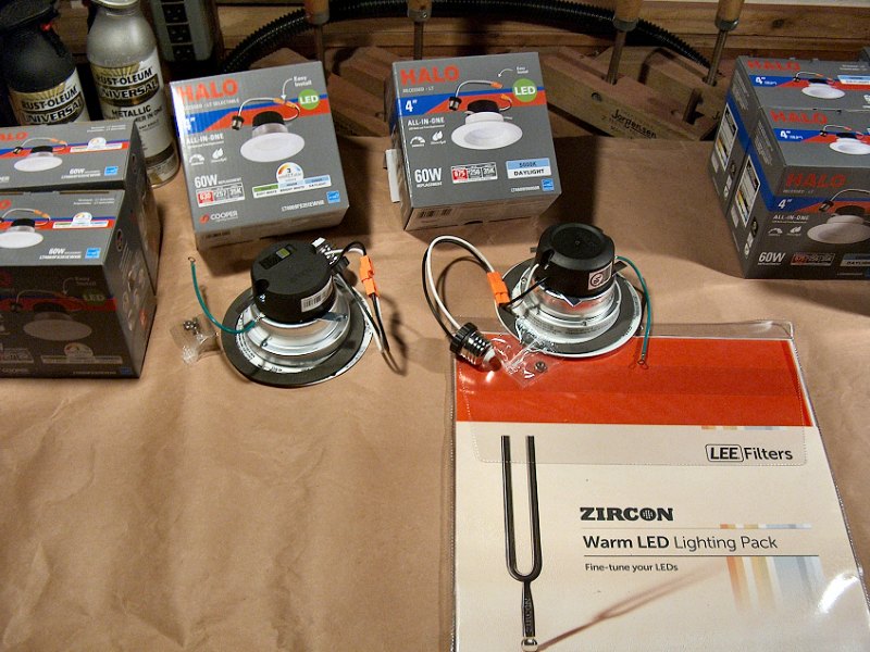 Working with the LED recessed light "retrofit kits" (5 photos).
A bit more diggin' around on the 'net led me to information about adding a filter gel to the thing to "warm it up". Apparently I'm
not the only one that doesn't like the look of recessed LED lights, and folks are playing with photography lighting filters to try and get things
warmed up. I started with a set of Color Temperature Orange (CTO) filters that came as a set with full CTO, ½ CTO, and ¼ CTO gels.
I then disassembled the LED retrofit fixture, used the lens to trace a cut line on the gel, and re-assembled the thing with the filter inside.
With the LED set to 5,000K, the ¼ CTO gave a nice glow when at full brightness, but when dimmed down it looked like Halloween out
there — way too orange! Setting the LED to "warmer" color temps. made it even more orange. This just wasn't working out as I'd like.
More diggin' around and I found what looked to be a proper solution from
Knight Sound & Lighting![]() with their Lee® Filters Zircon LED filters. I got their "Warm LED Lighting Pack", which has 12 different 1-foot
square gels. I figure I could try them in a couple lights for side-by-side comparisons, then get more of whatever color gel we decided looked best to
put in all our recessed fixtures. After lots of cutting and fussin' with fixtures, the #807 "Warm Amber 4" did the job perfectly with the
LED set to 5,000K. The engawa fixtures were all fitted with the Halo® retrofit kits and filters,
and with that all the exterior perimeter lights were upgraded to LED.
with their Lee® Filters Zircon LED filters. I got their "Warm LED Lighting Pack", which has 12 different 1-foot
square gels. I figure I could try them in a couple lights for side-by-side comparisons, then get more of whatever color gel we decided looked best to
put in all our recessed fixtures. After lots of cutting and fussin' with fixtures, the #807 "Warm Amber 4" did the job perfectly with the
LED set to 5,000K. The engawa fixtures were all fitted with the Halo® retrofit kits and filters,
and with that all the exterior perimeter lights were upgraded to LED.
The 4-inch cans for the kitchen task lights were another matter… Even with all the different filters and selectable color temp. LEDs, the
side-by-side difference in color with the old 50w Halogen bulbs just never looked right. Some of them were fine at full brightness, but when
they dimmed down the color would go way orange, or end up looking sorta grey (which is pretty gross when shed on foodstuffs). As
a last resort, I tried one of the PAR20 LEDs that had been in the engawa fixtures and it looked fine! I had a few bulbs
available from replacing burned out lights out there, so I went about getting replacements that matched for all the kitchen lights —
easier said than done. After a bit of searching, I was able to find the correct match from Bulbs
Depot![]() with the GE® #93360 LED PAR20
bulb (Yes, there are seven different kinds of GE® PAR20 LEDs). We went through the same comparison exercise with a couple
6-inch LED retrofit kits and the other cans in the kitchen, with much the same results. After wasting some bucks on a pair of 6-inch kits,
we ended up just replacing the 75w Halogen PAR30 bulbs with 11w Sunco™ Lighting PAR30 bulbs at 2,700K. The color is nice at all dimming
levels, and they fit well in the adjustable angle trim cans in the genkan without any problems. We ended up with
the 4-inch kits and the two 6-inch kits that we'll never use, but at least I know we won't be getting more 6-inch kits for the rest of the
house. I also won't need to monkey around with taking them all apart and painting the trims and baffles. These new LEDs should last many
years, and we've certainly noticed a significant change in our monthly electric costs now that many of our light fixtures are equipped with LEDs.
with the GE® #93360 LED PAR20
bulb (Yes, there are seven different kinds of GE® PAR20 LEDs). We went through the same comparison exercise with a couple
6-inch LED retrofit kits and the other cans in the kitchen, with much the same results. After wasting some bucks on a pair of 6-inch kits,
we ended up just replacing the 75w Halogen PAR30 bulbs with 11w Sunco™ Lighting PAR30 bulbs at 2,700K. The color is nice at all dimming
levels, and they fit well in the adjustable angle trim cans in the genkan without any problems. We ended up with
the 4-inch kits and the two 6-inch kits that we'll never use, but at least I know we won't be getting more 6-inch kits for the rest of the
house. I also won't need to monkey around with taking them all apart and painting the trims and baffles. These new LEDs should last many
years, and we've certainly noticed a significant change in our monthly electric costs now that many of our light fixtures are equipped with LEDs.
More LED Lighting Changes: Spring 2023
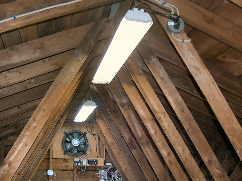
After some good progress on living room and attic renovation work, I spent a little time tinkerin' with a few remaining light fixtures that hadn't been changed to LED,
which were the fixtures with regular fluorescent bulbs and ballasts. The attic has four, 4-foot double-tube "shop lights" hung along the ridge board that work
okay for occasionally crawling around up there to get something out of storage, but they're pretty old, a couple of the tubes flicker a bit, they make an annoying humming
sound when they're on, and they often don't work at all when it's cold up there. I've also got one of these same fixtures out in the garden shed, and it suffers from
the same problems (flickers, hums, and rarely works in the Winter). So, the quick solution is to replace the standard T-10, 40w 4-foot fluorescent tube
with a "Type-A" LED, right? Nope. I tried that for the garden shed when one of the tubes burned out with an LED retrofit tube from the hardware store, but
it just doesn't work (a wasted $20 lesson learned).
 Changing the 4-foot fluorescents to LED (3 photos).
So here's the deal: T-8/T-10/T-12 retrofit LED tubes come in a few varieties. Type A replacements are "Ballast Compatible" units made to use the existing fluorescent fixture's ballast, so you just remove the fluorescent bulb and pop in the LED and you're done… as long as your fixture has a "compatible" ballast, and is fairly new to ensure the ballast is "good". If it's an old fixture, then this probably won't work. Type B replacements are "Ballast Bypass" units made for direct connection to 120VAC. Also known as "line voltage" lamps, these units have an internal LED driver so they require the fixture to be re-wired to bring line voltage to the lamp holders rather than have power supplied through the fixture's ballast. Type C replacements require an external LED driver/controller that again requires re-wiring to bypass the fixture's ballast (the "magnetic strip" tube replacement kits may be considered Type C replacements, even though they're not tubes). The Type C units usually have impressive dimming, color control options, and long lifespan, but they're also rather expensive compared to the Type A and Type B retrofit options. It would usually make more sense to just replace the entire fixture if the Type C control options are required. Finally, there's the Type A+B (formerly known as Type D) replacements which are both "Ballast Bypass & Compatible" units. These replacements allow you to either leave the ballast connected (assuming it's compatible to begin with), or re-wire the fixture for direct line voltage to the lamp holders. Of course, the Type A+B replacements are more costly then either the Type A or Type B.
While the simplest (and cheapest) route seems to be to just pop in a bunch of new Type A LEDs, the main goal is to enjoy the reduced energy needs of LED compared to fluorescent. Replacing a pair of 40w, 2800-lumen fluorescent tubes with a pair of 14w, 2200-lumen Type A LED tubes obviously drops the fixture's wattage from 80 to 28, but the fixture's ballast will still consume some power (not much, but a few watts at least). It seems much better to me to just bypass the ballast (which will eventually fail) and go with the Type B replacements. But wait, there's more! The Type B units need line voltage wired directly to the lampholder (the little plastic thing at the ends of the fixture, usually referred to as a "tombstone", since that's kinda what it looks like). Lampholder "tombstones" come in a couple of configurations as well, and the lampholder configuration for the fixture must be determined before purchasing the Type B replacements.
To address the lampholder configuration, we need to back track a bit and re-examine the guts of the fluorescent fixture. Assuming we're still talking about a two-lamp, 4-foot fixture, the fixture has four lampholders with two at each end. These are G-13 bi-pin sockets designed to hold T-8, T-10, or T-12 fluorescent tubes. The pins on each end of the tube are the same distance apart: 13mm, hence the name G-13. However the tubes are different diameters, which are a result of how many eights of an inch the model number indicates… So a T-8 tube is eight eighths, or 1" in diameter, a T-10 is ten eighths, or 1-1/4", and a T-12 is twelve eights, or 1-1/2" (there's also the little G-5 bi-pin socket, with pins 5mm apart for the T-5, 5/8" tube). That's not a goofy mix of English and metric measurements at all! What we're really after here though is how each socket is wired to the fixture's ballast. If the fixture has an "instant start" ballast, it will have "shunted" tombstones — this means both contacts in the socket are connected to each other, either internally (which may only be determined with a multimeter), or with a small jumper wire at the base of the socket. Shunted tombstones usually just have one wire from the ballast to the tombstone. The other option would be for the fixture to have a "rapid start" ballast (and sometimes a little "starter" can), which then uses "non-shunted" tombstones. Non-shunted tombstones have isolated contacts with at least two wires going from the ballast to each tombstone. Where this becomes important when considering LED replacement tubes is that the tubes are available either as "single-ended" power or "double-ended" power tubes. Single-ended tubes only require power at one end of the tube, with one pin connected to power/black, and the other pin connected to neutral/white. The other end of a single-ended power LED tube has no wiring connected to the socket, and the socket merely holds the tube in the fixture. Single-ended tubes must be installed with non-shunted tombstones. Double-ended tubes require connections at both ends of the tube, with one end connected to power/black, and the other end connected to neutral/white. Doubled-ended tubes may be installed in either shunted or non-shunted tombstones. Type A and Type A+B replacements always require double-ended power in order to maintain backward compatibility. Type B replacements are usually single-ended power.
 The last couple fixtures get LEDs (2 photos).
All that blather boils down to my decision to replace my old 4-foot, T-10 fluorescent tubes with Type B, single-ended LED replacement tubes. Because a few of the
existing G-13 sockets were missing bits of plastic (even though they still held the old tubes okay), I also picked up a bag of 20 new, non-shunted
G-13 tombstones to replace all my old sockets ($14 for the bag, so no biggie). We've been happy with the performance of the Sunco™ LEDs that
have gone in all the recessed light fixtures, so I purchased a 10-pack of their Type B, single-ended, 6,000K, 18w frosted T-8s for my fixtures ($80, or
$8 per bulb, from Amazon). An afternoon in the attic got all the fixtures up there swapped to LED, and wow what a difference! Most of those fluorescent tubes
were many years old, and that 40% luminosity depreciation over the life of the bulb was really noticeable as I got the fixtures upgraded. The LEDs are
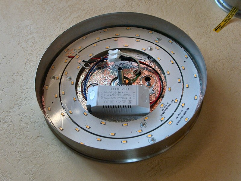
With the 4-foot tube fixtures in the attic and garden shed taken care of, all that remained was a flush-mount ceiling light in the kitchen (we call it the "groceries light", since we usually only turn it on if we're putting away groceries in the evening), and 2-foot, double-tube T-10 fluorescent ceiling fixture in the utility room. The kitchen light uses a 22w, T-5 circline fluorescent tube with a 2GX13 quad-pin base, and there really isn't a direct replacement LED tube available for that (basically no such thing as a Type A, ballast compatible, round LED as far as I can tell). There are a few replacement options available that I suppose we could call Type B or Type C, in that they all require re-wiring the fixture for the LED driver, and some even have their own control units for dimming and color temp. I went with a LEDY 33w, 3,630 lumen unit in "warm white". The LED just fit inside the lamp fixture, and even though the LED uses more wattage than the fluorescent (33w versus the 22w for the old tube), the brightness of the LED (3,630 lumen versus 1,900) and warmer color provides much better, more useful lighting for the kitchen. The upgrade for the 2-foot utility room fixture was basically the same as what was done for the 4-footers: remove the T-10, 20w tubes and ballast wiring, re-wire a pair of non-shunted tombstones, and pop in a couple Type B, single-ended power, 9w LED replacements. With the exception of the outdoor floodlights, all other lighting has been upgraded to LED. It's certainly brighter, and time will tell if it makes a noticeable difference in the electric bill.
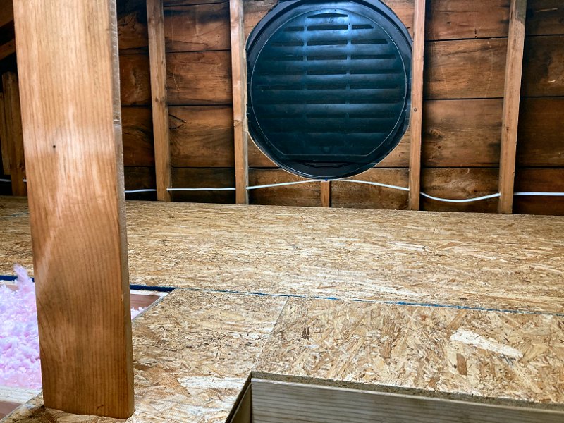
Extra Attic Ventilation: Fall 2018
Back in 2006 when we built out the new roof framing, I made sure we included plenty of attic ventilation
as part of that project. As mentioned above in the Dealing with Moisture section, there is a ridge vent the runs
the length of the house, and a soffit vent around the entire perimeter. When working on the siding
& trim in 2010, I also added a 36-inch diameter vent to one of the gables, with 16-inch diameter vent in the other, and the entire area
under each porch roof is screened for attic ventilation. All this ventilation is an important part of making the insulation in the attic do its
job — without adequate ventilation, an un-conditioned attic space will build up warmth during the heating season, likely causing snow and
ice on the roof to melt and form ice dams, and also create condensation that can reduce the effectiveness of insulation. During the cooling
season, a poorly ventilated attic can get very warm, creating a significant extra burden on air-conditioning equipment.
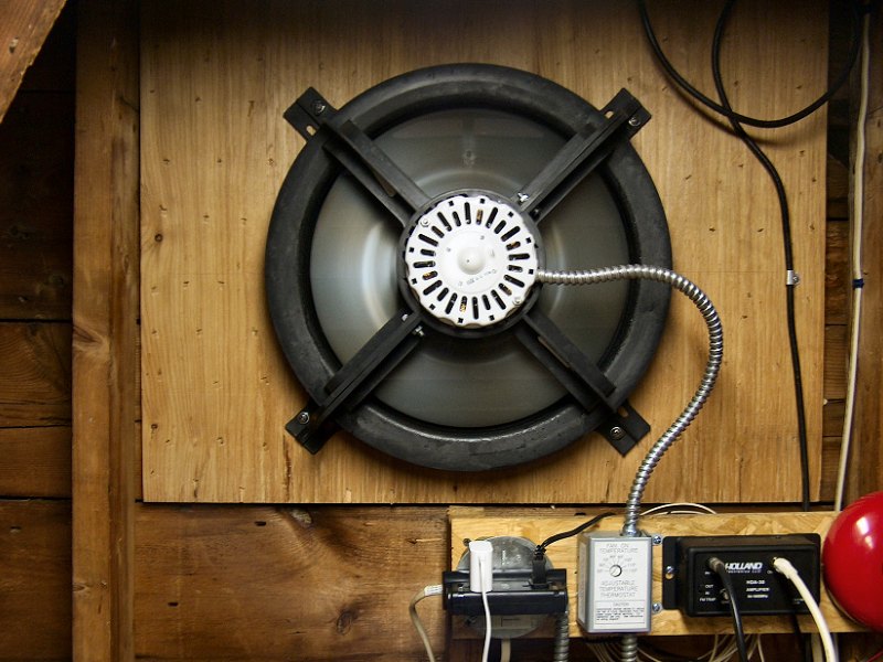 The powered attic gable vent fan.
We have plenty of "passive" ventilation with air moving through the attic from the "stack effect" (which basically just means warm air rises and cool air falls), in through the soffit vents, then up and out the ridge vent. While there hasn't been any insulation in some parts of the attic many years, the thermal barrier and insulation for the kitchen, bathroom, and genkan has been keeping house comfortable with reasonable heating and cooling costs. That changed fairly dramatically when we finally removed the old Homasote® ceiling panels from the living room in the Winter of 2017. We stapled up a temporary plastic vapor barrier to the ceiling joists after the panels were removed, but even that pathetic little 3/4-inch thick Homasote® offered some insulation value compared to a simple plastic sheet. We really noticed the difference the next Summer, when the house would remain very warm well into the evening on hot days, even with the air conditioner running all day. I was in no position to start installing a new ceiling, so as a temporary measure, I investigated adding some "active" ventilation to the attic to get that hot air out of there.
I decided to get an Air
Vent® ![]() Model #53315 Gable Attic Ventilator through Amazon, and got that installed in the attic at the end of that Summer to see if it would
help the situation. The unit I selected has a 14-inch fan blade, so it fit nicely over the 16-inch gable vent where the main attic meets
the entry area. It's hardwired in to 120v, and has a small thermostatic control to turn the fan on at whatever temperature you select (we set
it to 100°). I also picked up a set of Sorbothane® "anti-vibration" mounting washers to help
keep the thing quiet. To get it mounted, I started with a piece of 1/4-inch Oak plywood cut to fit within the framing of the gable end,
with a 14-inch hole for the fan at the vent opening. That plywood was given a generous slather of construction adhesive, then I went nuts with
the narrow-crown stapler to ensure it was well bonded to the old, uneven, original sheathing boards. The fan housing was then attached with
stainless-steel hardware and the anti-vibration washers, then finally wired into a nearby junction box to share power with the attic lighting
circuit. It's been working very well at keeping the attic the same temperature as outside, and on even the hottest Summer days
it shuts off as soon as the sun moves off the roof. We've also noticed a big difference in how much the air-conditioner is working in the
evenings. It's a little loud, but that should change once we actually get some insulation in the living room ceiling.
Model #53315 Gable Attic Ventilator through Amazon, and got that installed in the attic at the end of that Summer to see if it would
help the situation. The unit I selected has a 14-inch fan blade, so it fit nicely over the 16-inch gable vent where the main attic meets
the entry area. It's hardwired in to 120v, and has a small thermostatic control to turn the fan on at whatever temperature you select (we set
it to 100°). I also picked up a set of Sorbothane® "anti-vibration" mounting washers to help
keep the thing quiet. To get it mounted, I started with a piece of 1/4-inch Oak plywood cut to fit within the framing of the gable end,
with a 14-inch hole for the fan at the vent opening. That plywood was given a generous slather of construction adhesive, then I went nuts with
the narrow-crown stapler to ensure it was well bonded to the old, uneven, original sheathing boards. The fan housing was then attached with
stainless-steel hardware and the anti-vibration washers, then finally wired into a nearby junction box to share power with the attic lighting
circuit. It's been working very well at keeping the attic the same temperature as outside, and on even the hottest Summer days
it shuts off as soon as the sun moves off the roof. We've also noticed a big difference in how much the air-conditioner is working in the
evenings. It's a little loud, but that should change once we actually get some insulation in the living room ceiling.
The Expensive Stuff
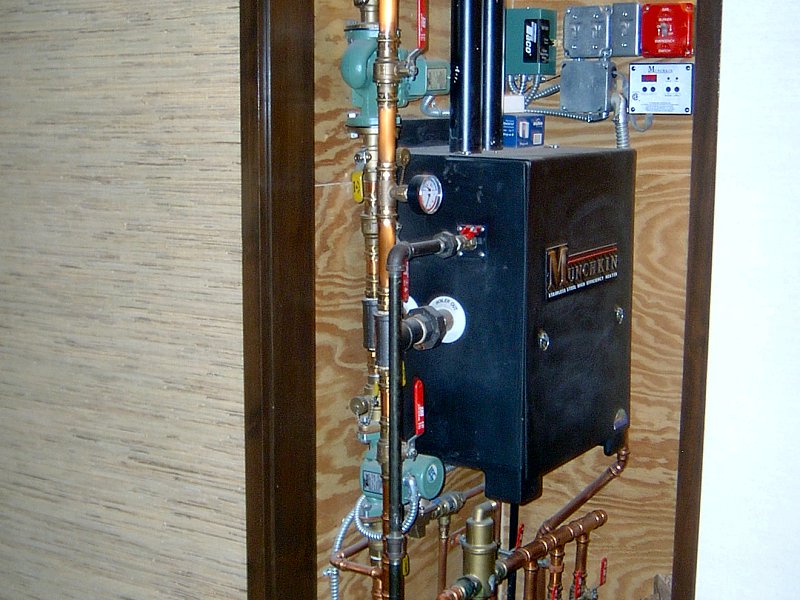 The installed Munchkin™ T80M.
Improving the Heating & Cooling Systems
Upgrading the heating and cooling systems would usally be an expensive proposition that most homeowners don't
undertake lightly, but since we had a 50-year old furnace and no air conditioning when we started the renovation, this
one's easy — we got to purchase the latest and greatest stuff, and enjoyed sizeable rebates and tax credits in the process.
For details of the upgraded heating and cooling equipment we're using, please see the HVAC
section. Details of the high-efficiency indirect water heating system can be found in the
Plumbing section.
Household Appliances
Household appliances are another area where we've needed to purchase all new units during the renovation, so we've been
able to select efficient Energy Star rated appliances for everything (otherwise swapping out perfectly good major appliances
for more energy efficient units is a costly endeavor). Our new major kitchen appliances include a microwave/range vent
combination unit, a refrigerator, a gas range, and a double-drawer dishwasher. We also recently purchased a new Energy
Star front-load washing machine (which automatically adjusts the water level based on the load), and a moisture sensing
electric clothes dryer.
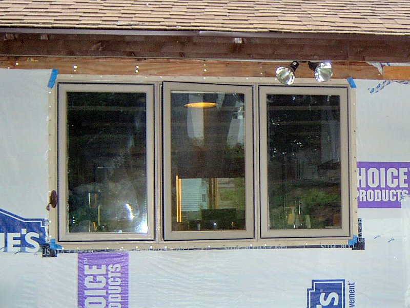 One of the new windows.
High Efficiency Windows & Doors
All windows and doors were replaced with Marvin Integrity®
![]() Wood-Ultrex Energy-Star
units (now sold as the Marvin Elevate™ collection). These are fiberglass-clad wood-cased windows and doors, with Low-E II Argon
filled double pane insulating glass. Typical thermal specs for the units are U-factor: 0.30; R-value: 3.33; Solar Heat Gain Coefficient:
0.31 and Visible Light Transmittance 0.54 (depending upon the unit style and size, the values vary buy a couple hundredths of a point here and there).
Each unit was installed and flashed according to the manufacturer's specifications (for complete installation details, please
see the Windows & Doors section.
Wood-Ultrex Energy-Star
units (now sold as the Marvin Elevate™ collection). These are fiberglass-clad wood-cased windows and doors, with Low-E II Argon
filled double pane insulating glass. Typical thermal specs for the units are U-factor: 0.30; R-value: 3.33; Solar Heat Gain Coefficient:
0.31 and Visible Light Transmittance 0.54 (depending upon the unit style and size, the values vary buy a couple hundredths of a point here and there).
Each unit was installed and flashed according to the manufacturer's specifications (for complete installation details, please
see the Windows & Doors section.
↑
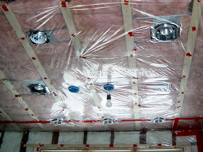
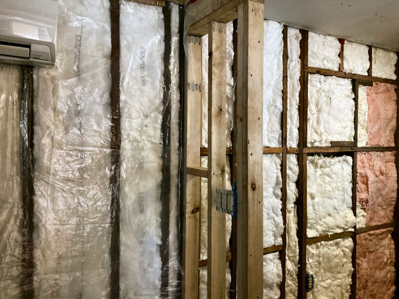
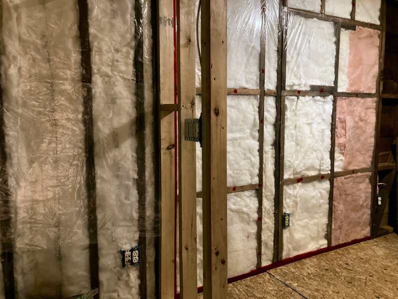
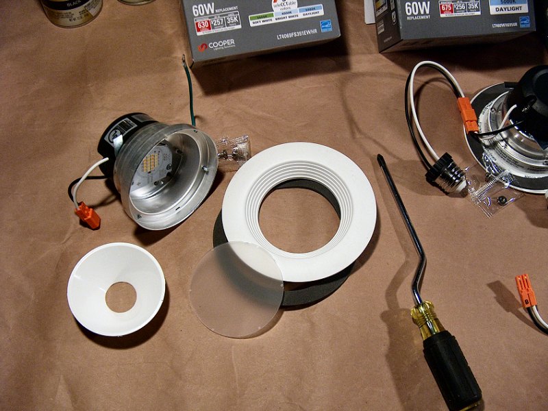
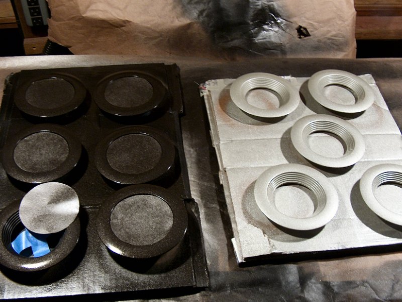
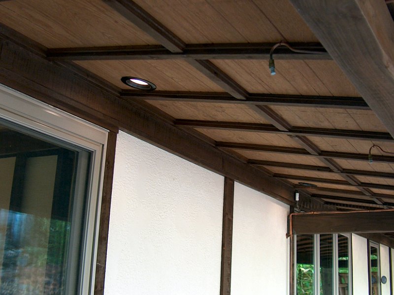
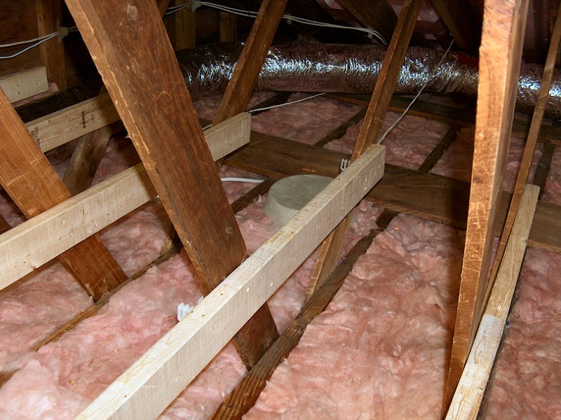
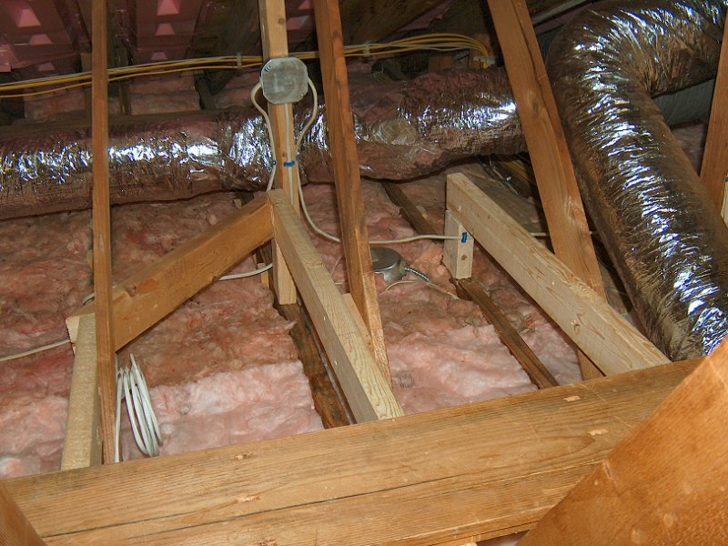
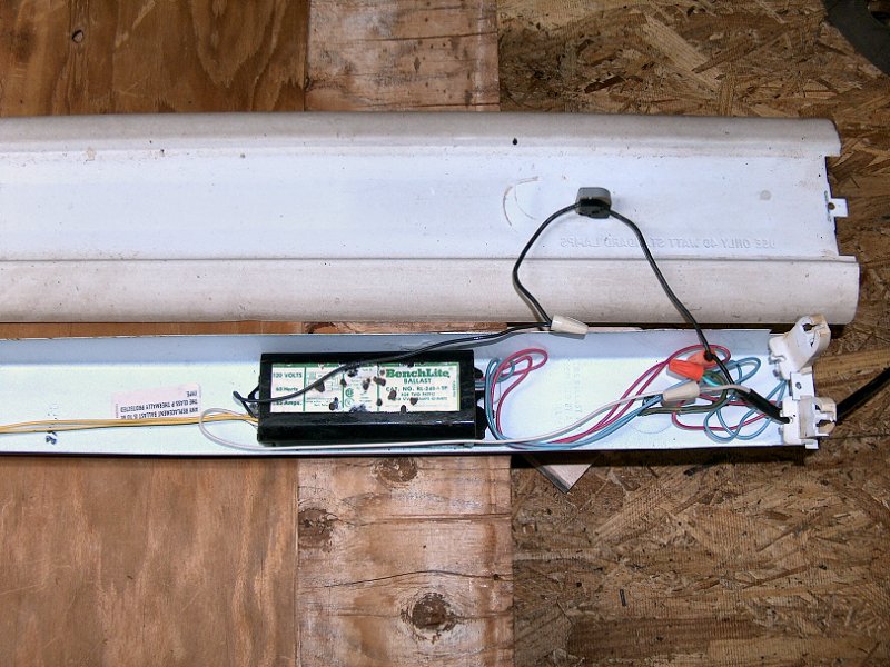
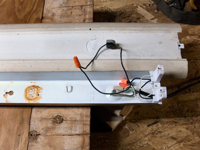
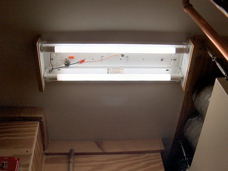
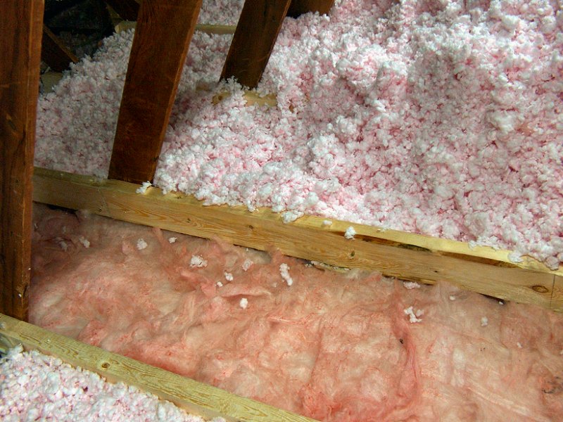
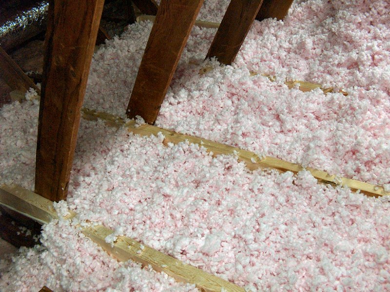
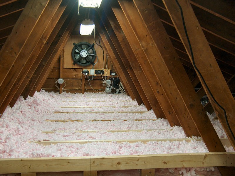
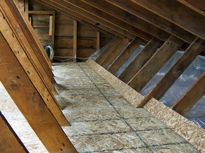
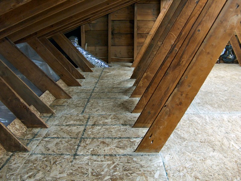
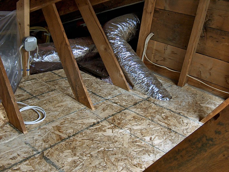
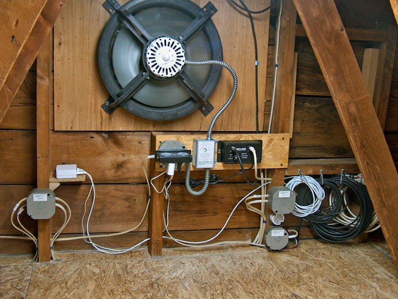
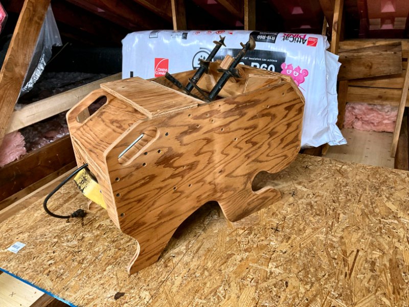
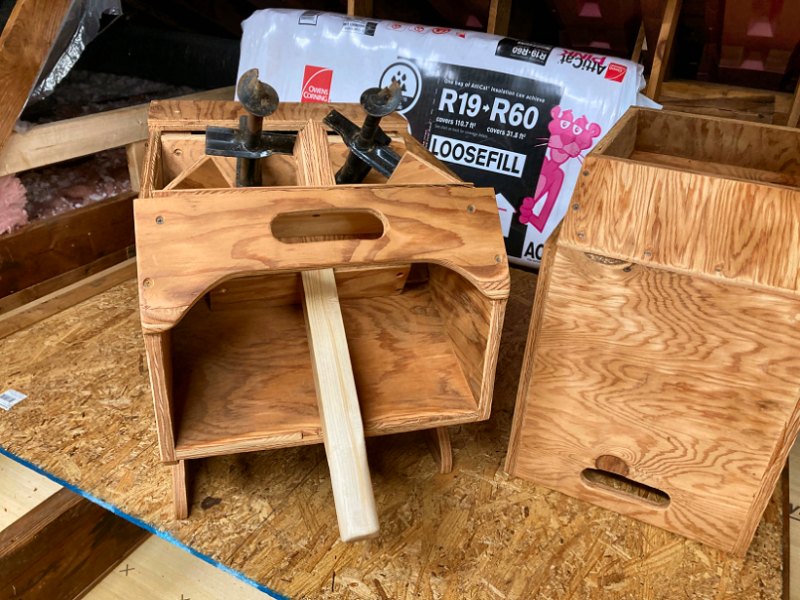
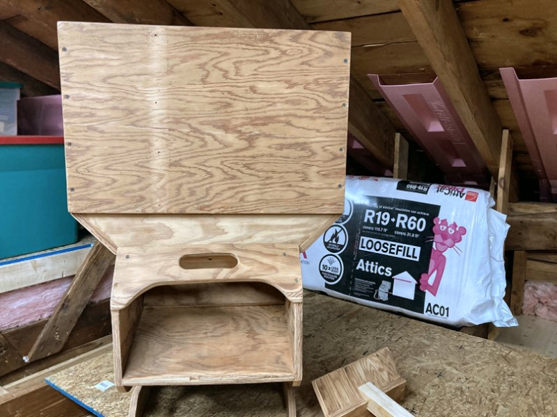
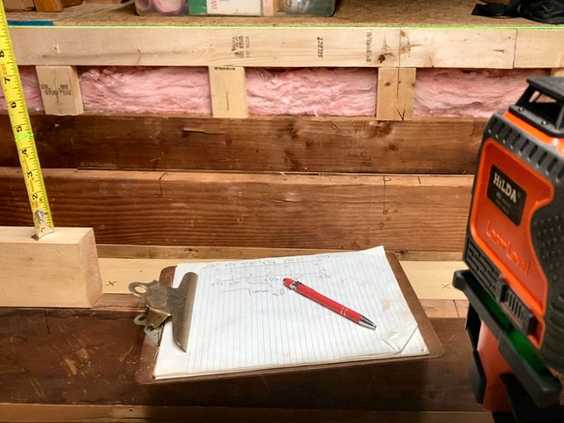
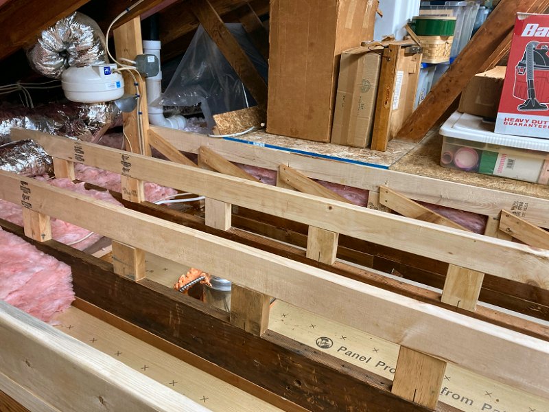
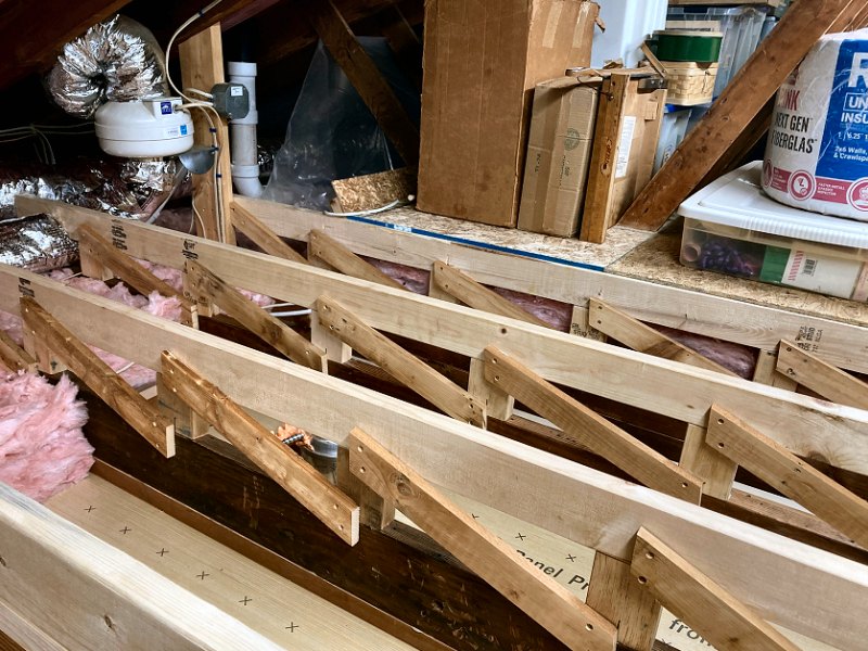
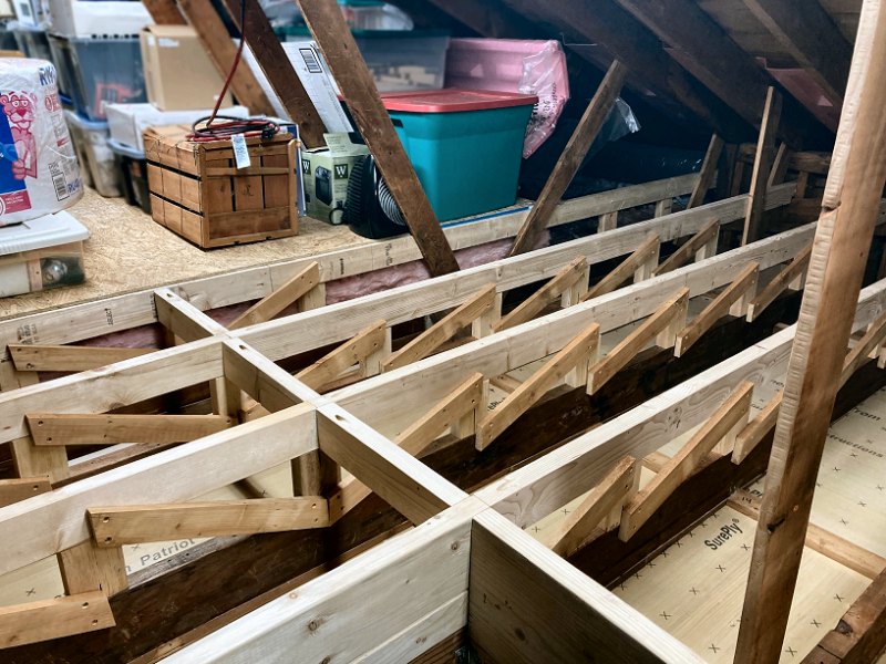
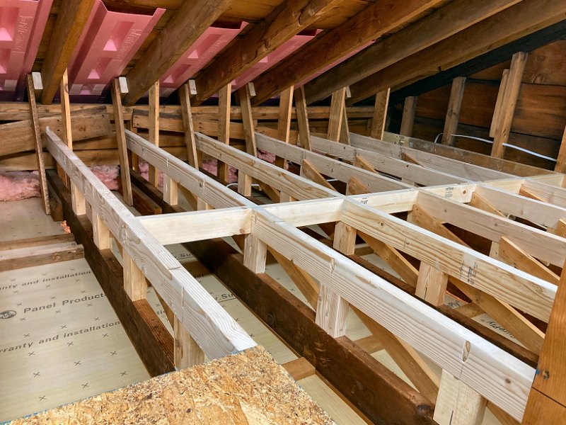
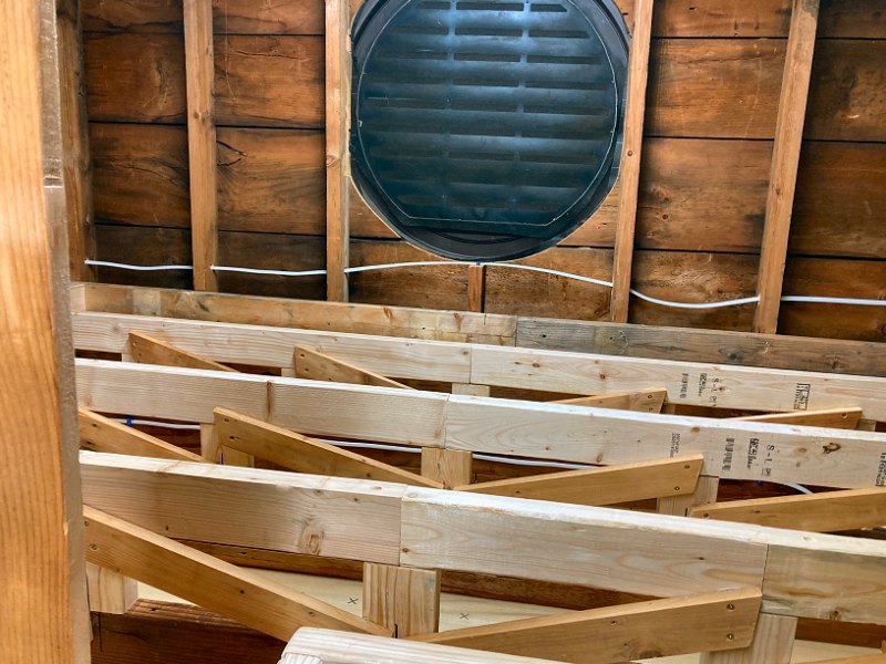
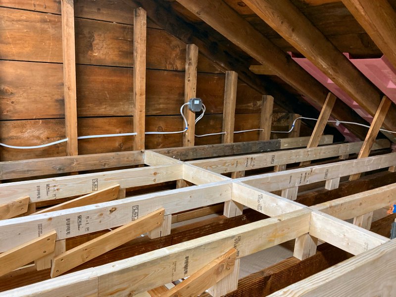
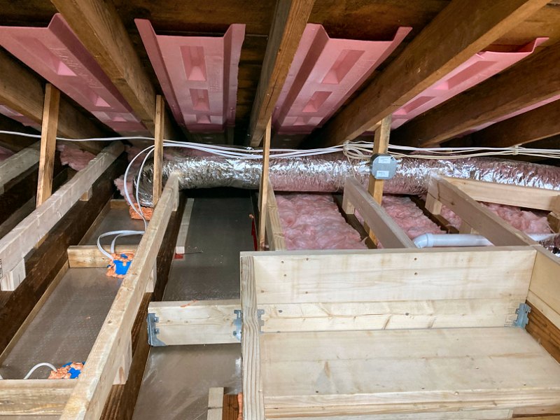
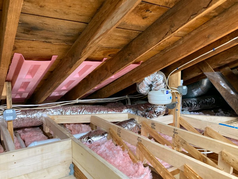
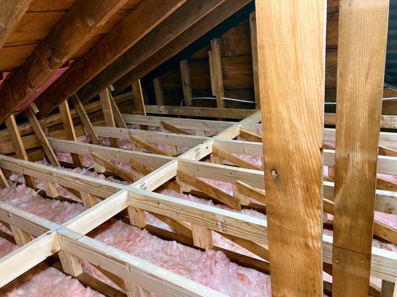
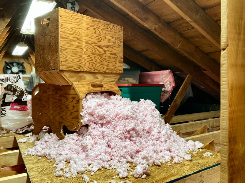
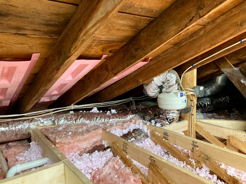
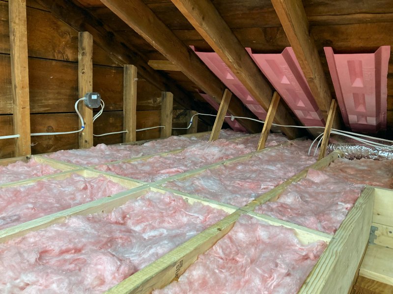
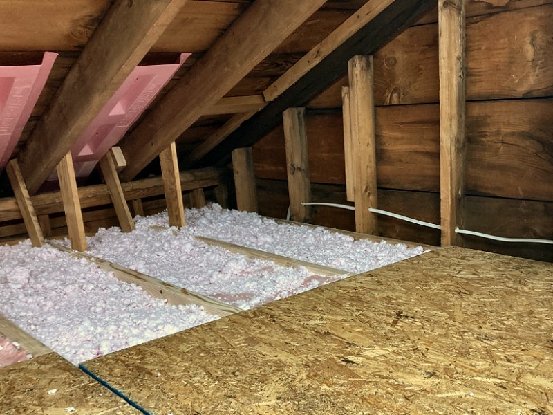
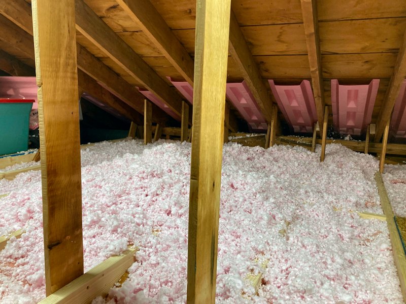
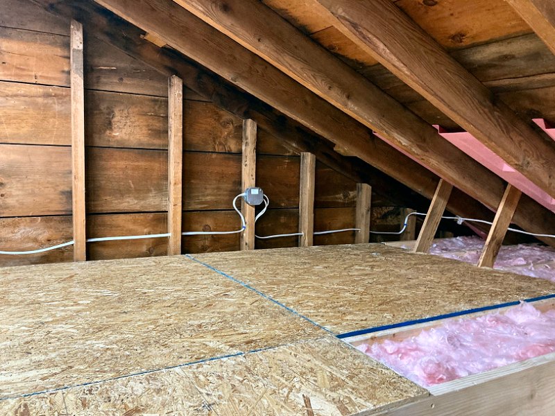
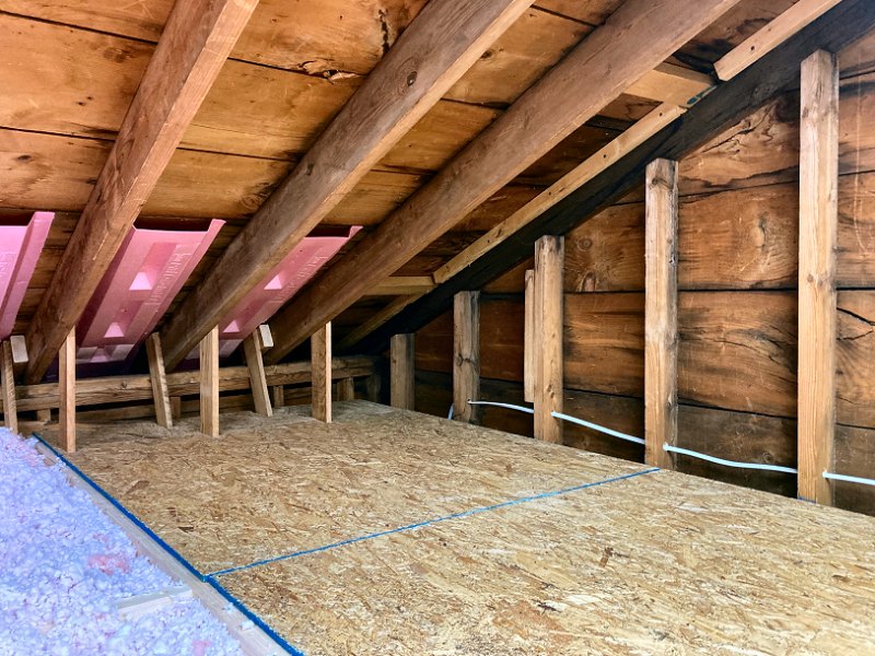
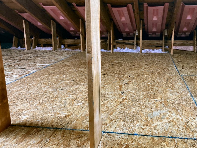
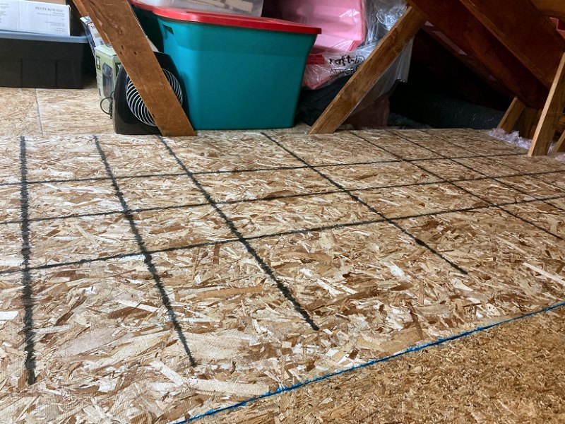
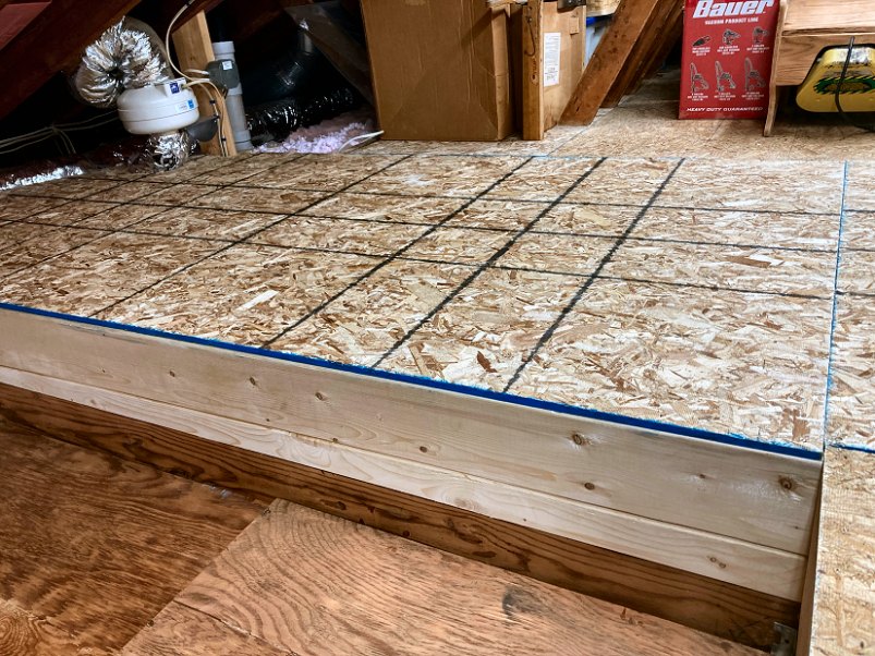
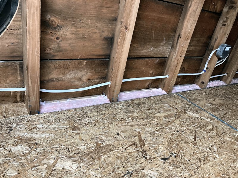
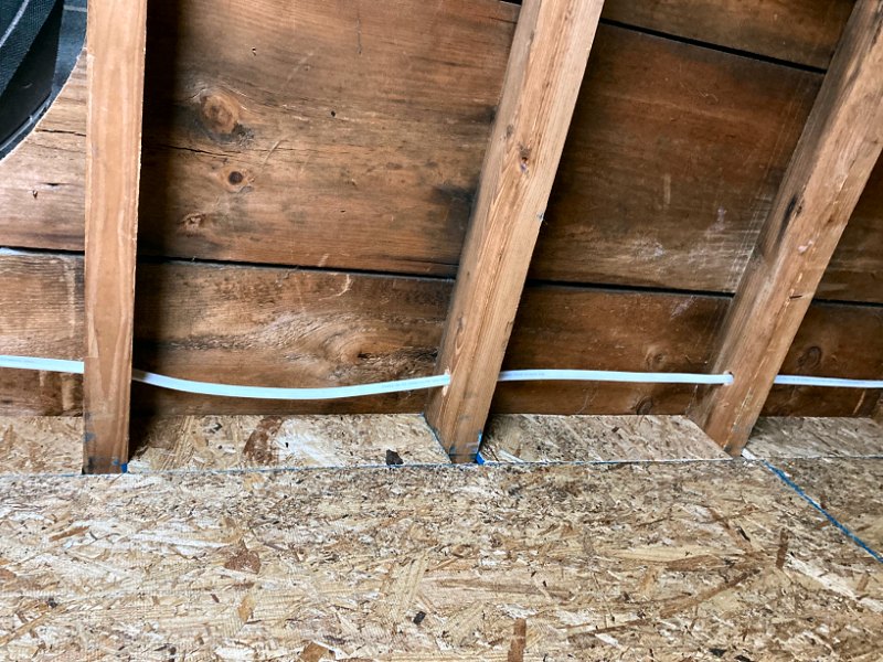
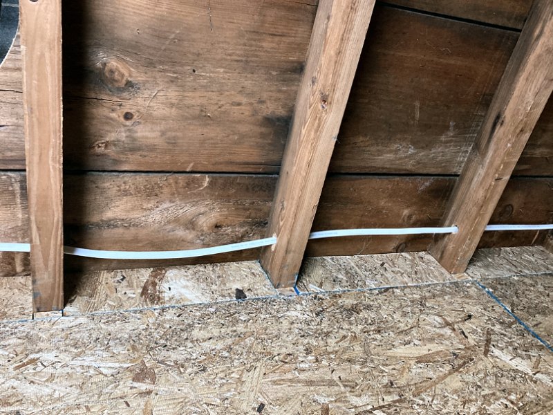
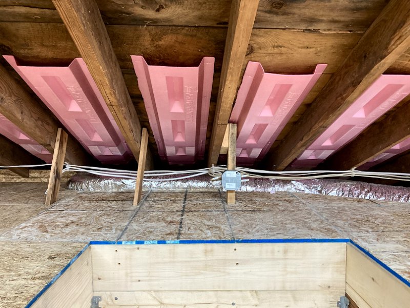
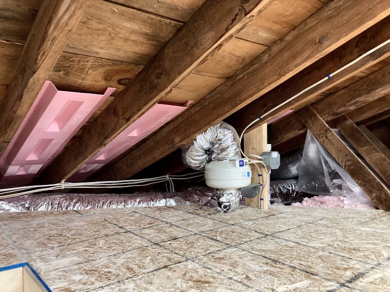
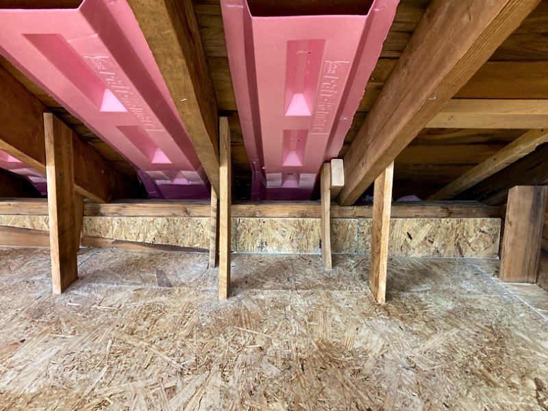
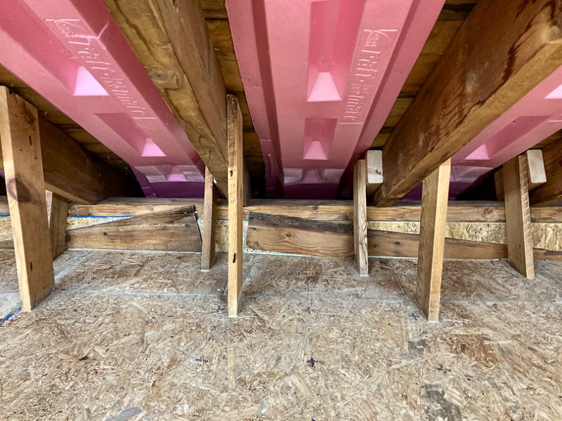
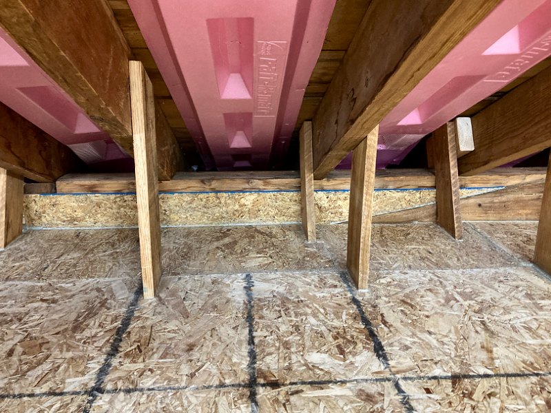
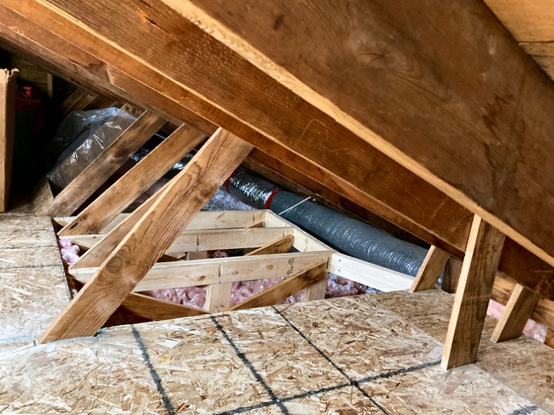
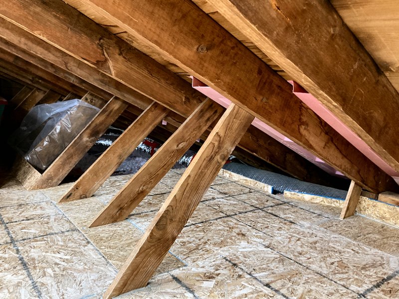
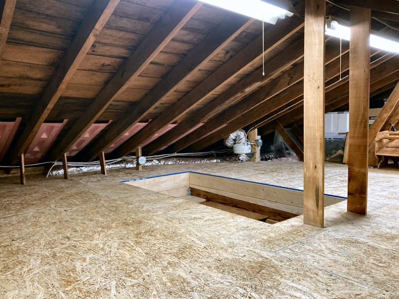
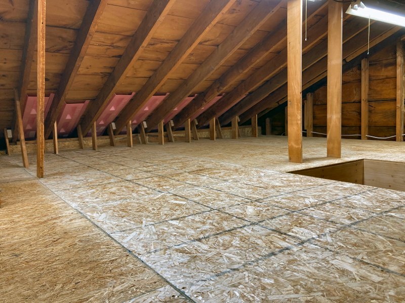
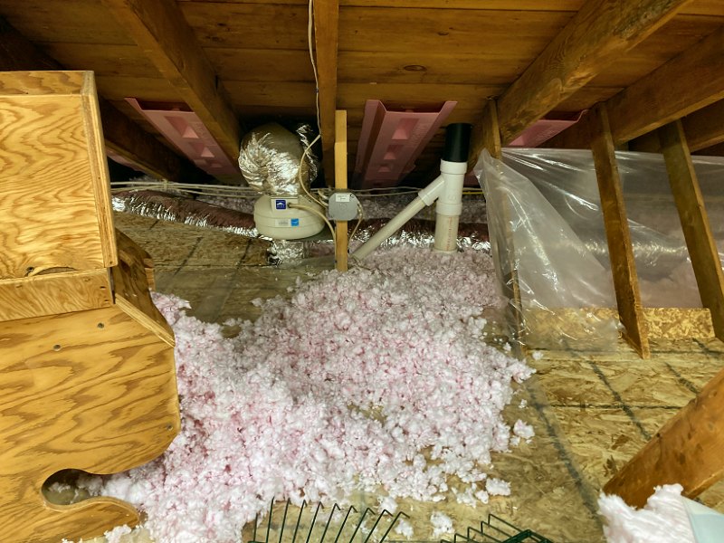
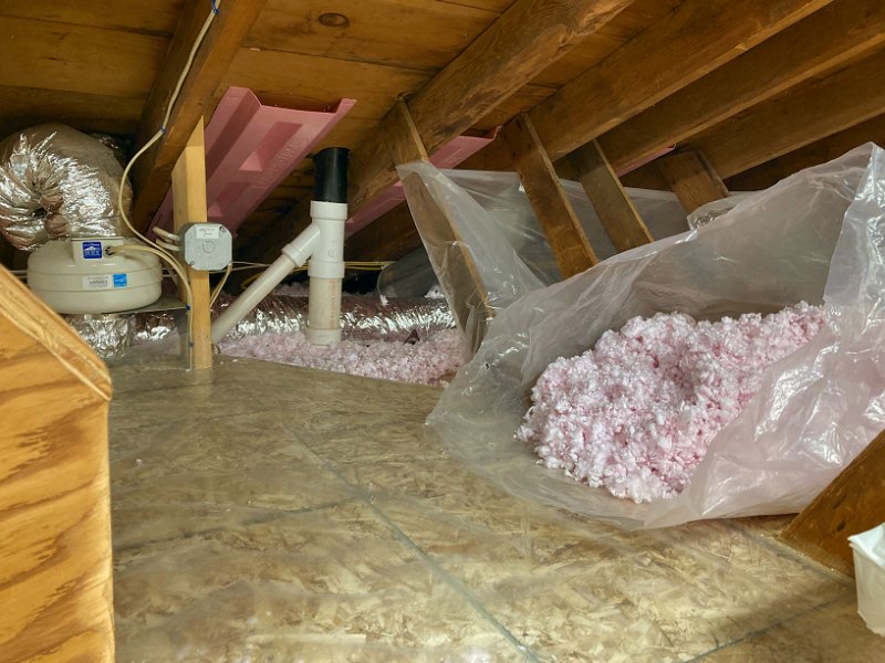
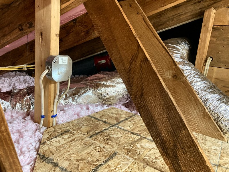
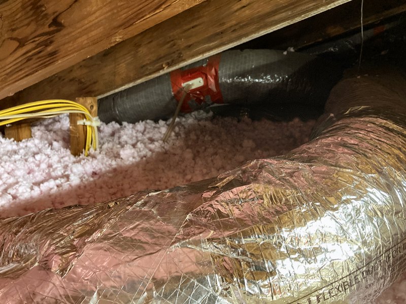
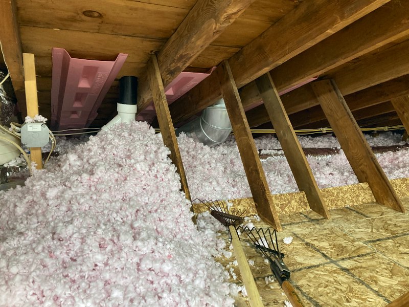
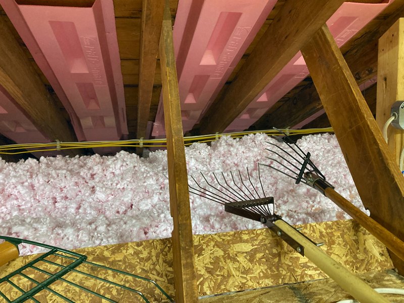
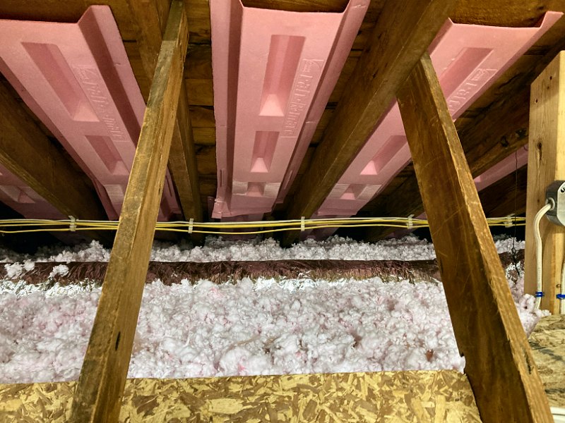
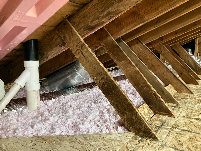