

The Woodworking Bench
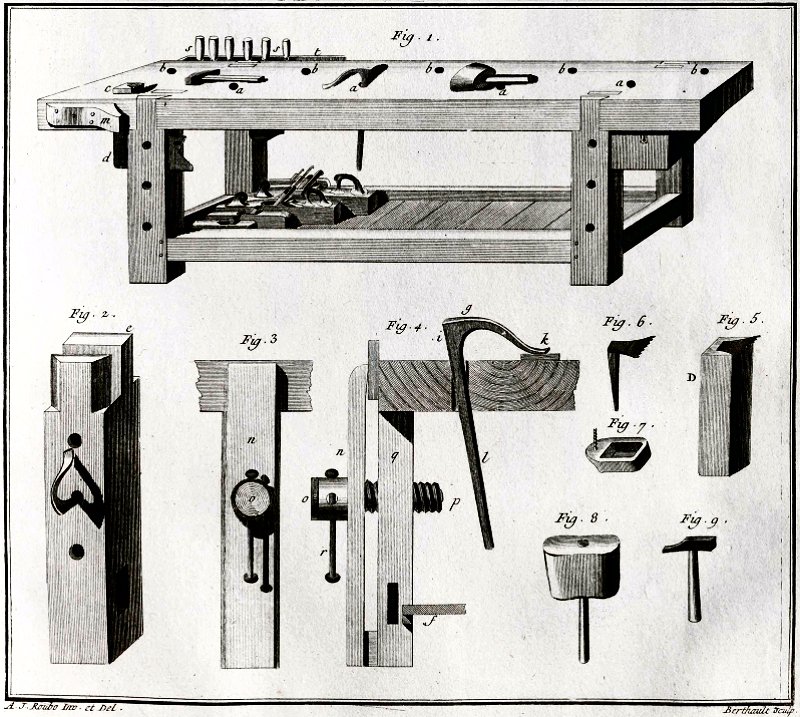
The "French" Bench, detail of Plate XI
Andre Roubo's The Art of the Joiner, vol I, ca.1769-1774.
I've been working on the KesterHouse renovation in one form or another for well over ten years now, and when ever I've had to do some special roof rafter cutting, custom framing joints, or finish carpentry work, I've somehow muddled through working on a pile of lumber with an old door on top, all stacked on a couple rickety plastic folding sawhorses. That's just silly. As I move forward with more interior work, I'm finding I really need to get myself a proper workbench so I can hold the stock I'm working — whether it's just to do some sanding and finish application, or for hand planing and working on various joints for finish trim. Wobbly stuff piled on sawhorses with clamps I always have to move as I work on each piece of stock just ain't makin' it anymore.
I suppose I could just screw down a nice solid-core door to a pair of sturdy wooden sawhorses and call it done, but come on — you know me better than that by now… I started thinking about what manner of bench to build after reading Christopher Schwarz's Workbenches a couple years ago, and followed that with The Workbench Design Book. Schwarz is a big fan of Roubo's massive bench that was described in his The Art of the Joiner, vol. I, published in 1769. Schwarz described and built Roubo's bench, refered to as the "French style", and also built a bench usually attributed to Peter Nicholson as the "English style" bench. The popularity of both bench types soared in the last few years, and there are many companies around now selling kits, plans, and fixtures for these centuries old bench designs (and some of them, while very nice, are incredibly expensive). Rather than spend thousands to buy a beautiful pre-made bench (that's going to end up in a plastic storage garage for at least a year), it's time I finally made myself a proper woodworking workbench.
Table of Contents
This joiner's bench page seems to be turning in to my joiner's bench book, so I've added this table of contents to help navigate to the various sections.
- Bench History & Design examines what I'm basing the bench design on, and ends with the initial plans for my design.
- Building the Joiner's Bench walks through each step of construction for the bench base, apron, and top.
- Stock Preparation: Selection of the materials and initial prep.
- Leg Cutting & Glue-up: Starting with the legs, the stock is cut and glued up for thickness.
- Leg Mortise & Tenon Work: Details the preparation of the two leg assemblies.
- Leg Unit Assembly & Drawboring: The leg assemblies are put together with drawboring.
- Base Stretcher Assembly & Bench Bolts: Tying the two leg assemblies together with the base stretchers.
- Top Stretcher Installation: The final piece of stock for the base is installed.
- Base Assembly & Workholding Hardware Installation: A few pieces of hardware are added to the base prior to finish application.
- Base Finish Prep & Application: The base is completed, edges dealt with, and finish applied.
- The Front Apron: Work begins on the apron with hole layout.
- More Front Apron Work: The apron backer board is screwed and glued into position.
- The Tail Vise Frame: Before moving to top assembly, the frame for the tail vise is built.
- The Tail Vise Jaw: The main tail vise jaw is assembled using the "Condor Tails" joint.
- The Bench Top: Construction begins on the split bench top, with another plan sheet of holdfast holes layout.
- The Front Top Laminate: The front half of the split top is screwed and glued together.
- The Bench Top Cross-members: Are created to connect the two halves of the split top assembly.
- Completing the Bench Base Unit Assembly: The rear half of the top is laminated, attached to the cross-members, and top finish is applied.
- Workholding Fixtures & Vises examines the installation of planing stops, the sliding deadman, and the tail and leg vises.
- The Center Planing Stop Strip: The filler strip for the split top is created, with stepped blocks to raise it for use as a transverse planing stop.
- Bench Top Planing Stops & Dowel Former: Two planing stops are added to the left end of the bench, as well as a dowel former plate.
- Tail Vise Assembly & Installation: The tail vise is finally finished and installed, along with a foot pedal to operate it.
- Leg Vise & Paralell Guide Work: The leg vise and parallel guide are assembled, vise screw adjusted, and the leg vise is finished and installed.
- The Sliding Deadman: This lengthy section addresses deadman assembly, and what I did to make use of my Stanley No. 203 Bench Brackets.
- Wooden Bench Dogs: These were made to occupy the blind dog holes along the front of the bench top and prevent them from filling with debris.
- The Apron Dog Lifter: With all those blind dog holes filled with dogs, I made this contraption to pop the dogs up for easy removal.
- The Double-Screw Vise: Assembly of this bench top unit allows comfortable work on the ends of vertically held stock.
- Bench Hooks & Shooting Boards: A few chunks of scrap turned into a very handy couple of bench hooks, a shooting board, and a sticking board.
- Tool Storage & Shelving covers the addition of the bottom shelf, bench top tool racks, powering the bench, and the tool box.
- The Bottom Shelf: The 5/4 stock that's been kickin' around the shop for months is finally put to use for the bottom shelf.
- Bench Top Tool Racks: Two un-planned tool racks are added to the back edges of each end of the bench.
- Bench Tool Storage Box: Work on the 4-drawer tool storage box for the right side of the bench shelf.
- Power Distribution & Task Lighting: While working on the tool racks, I decided to add some power outlets and additional task lighting.
- Bench Materials & Costs is a detailed list of materials and the entire cost of the project.
- Resources & References has links to a few bench building blogs, and a list of reference books utilized throughout the build.
Bench History & Design
The short-term goal for my bench is to build something I can use to secure my stock for trim and finish carpentry prep work. We now call that work finish carpentry, but 100 years ago this manner of woodwork was referred to as joiners work (as opposed to cabinetmaking - what we call case work now). Eventually I'll have a lot of cabinetmaking / case work to do to furnish the house when the renovation is finished, but I need to get the renovation finished first. While I admire the French style bench, I'm more interested in getting something together fairly quickly and without spending too much money on it. I'd also like the ability to knock it down in to managable parts so I can move it to the garage someday.

The Joiner's Bench, Fig. 12, Joinery Plate XII
Peter Nicholson's Mechanic's Companion, ca.1831.
To repeat Schwarz's bench design mantra, the bench needs to hold stock so I can work the edge, face, and ends without issues. For what I have in mind, I believe the English style bench is going to do the job nicely. Most of the elements for joiner's bench design seem to have been worked out over the last couple hundred years, so that means a little historical study is helpful to narrow down the design. In addition to Schwarz's wonderful books, Landis's The Workbench Book also offers some interesting design ideas, and most recently Mike Siemsen created the DVD The Naked Woodworker, which features building a Nicholson bench with dimensional lumber over just a couple days.
Drawing upon all these resources I based my design largely on the Nicholson bench (shown at right), with the workholding additions
(leg and tail vise) from Schwarz's first workbench book, then tweaked it a bit using some of the knock-down joints he utilized on his
recent blog posts at Lost Art Press
![]() I like the Nicholson because
it doesn't require the massive laminations (or solid slabs) used for the top and legs on the Roubo, but instead utilizes the large
front apron to tie into the legs and provide dimensional stability. I also got rid of the large rear apron that many others added to
the back (most notably George Ellis, in his 1902 rendering of the English bench, below), since I believe the original open back allows better
access for clamping the far end of stock to the bench. Ellis also improved on the original with his splayed legs to resist planing thrust,
as well as the storage drawer and bottom shelf, which I've also incorporated into my design.
I like the Nicholson because
it doesn't require the massive laminations (or solid slabs) used for the top and legs on the Roubo, but instead utilizes the large
front apron to tie into the legs and provide dimensional stability. I also got rid of the large rear apron that many others added to
the back (most notably George Ellis, in his 1902 rendering of the English bench, below), since I believe the original open back allows better
access for clamping the far end of stock to the bench. Ellis also improved on the original with his splayed legs to resist planing thrust,
as well as the storage drawer and bottom shelf, which I've also incorporated into my design.

The Joiner's Bench, Fig. 1, Chpt. III, Workshop Appliance &c.
George Ellis's Modern Practical Joinery, ca.1902.
Another design element I found very interesting is from the bench in Charles Hayward's How to Make Woodwork Tools printed in London in 1945. Hayward incorporates the wide front apron of the original Nicholson design to add rigidity, and also like the original, he does not have a matching rear apron. However, the change he made that I really like is that slightly angled rear leg system, (shown below) which like Ellis's splayed legs, helps stabilize the bench during rigourous hand planing operations. Perhaps because of my years of fighting with wobbly sawhorses when trying to hand plane, I decided to add Hayward's angled rear legs to my bench. He also ties the two sets of legs together with a lap jointed spreader at the top of the rear legs, rather then just the two mortise and tenoned spreaders at the bottom. These tweaks from Hayward have been worked into my design, and yes, that means cutting some compound angled pieces, including angled mortise and tenons, to tie it all together.

The "Home Workshop" Bench, Fig. 1
Charles H. Hayward's How to Make Woodwork Tools, ca.1945.
One element that didn't change much over the well documented 150 year history of the English joiner's bench described above, is the method of workholding these gentlemen utilized on their bench designs. Common to all of them, even going back to Félebien in 1676 or Moxon in 1678, is the simple planing stop block that's mortised into the left end of the bench top (Fig.5 & Fig.6 in Roubo's plate XI, above), fitted with a toothed, iron insert to grip the end of a board while planing. Holes in the front apron and legs are shown in both Félebien's and Moxon's plates, although these are likely for holdfasts (Fig.2 & Fig.4 in plate XI), like the holes in the bench top. Félebien didn't show any manner of vise or clamp on the front of his bench, although Moxon did add a crochet or hook (like Roubo's) on the front, which included a wooden screw to clamp boards in place for edge work. This crochet evolved into the face vise on Nicholson's bench, and Ellis shows a small peg at the far right to support the other end of the board, as does Hayward. An early tail vise and row of dog holes shows up in what Roubo calls the German cabinetmaker's bench (more likely Scandinavian) in plate CCLXXIX of his The Art of the Joiner, vol. III of the early 1770s. Schwarz incorporates both the leg vise on the front left, at a 20° angle, and a wagon / tail vise with a row of dog holes in the top. My bench will make use of the leg vise and tail vise, and of course holdfasts and a planing stop in addition to a row of dog holes for work holding.
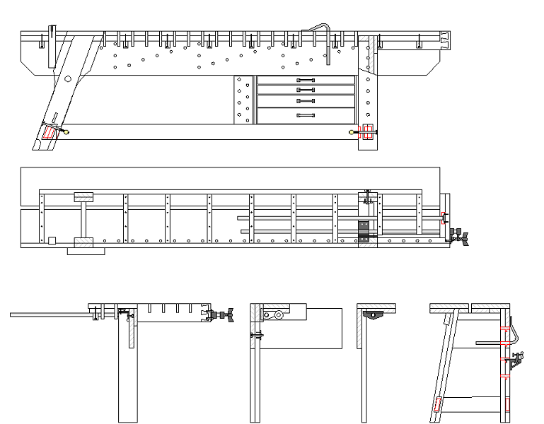
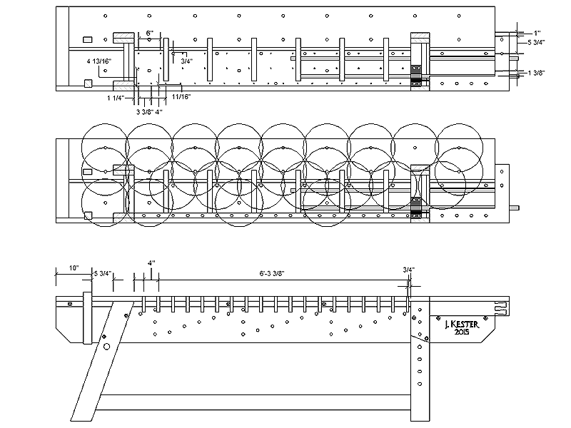
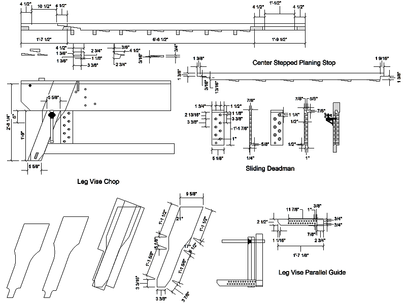
The general layout of my 10' joiner's bench (1 sheet).
With a pretty good idea of what I wanted as an end result, I set about making a set of plans to get things started. My workspace will accomodate a 10 foot long bench without too much trouble, and that length will allow me easily secure standard 8 foot long lumber for making trim pieces. The overall bench design is a combination of Schwarz's English bench from his first book, along with a sprinkling of changes from other historical sources outlined above. Both back legs will get sloped toward the front at a 10° angle (from Hayward), and both left legs will get a 20° slope toward the center (Ellis/Schwarz). The right front leg will not be sloped, but I plan to add an angled semi-dovetail to the top where it joins the apron, as Nicholson shows. The leg pairs will be through tenoned top and bottom with a wide board at the top, and a double-thick spreader at the bottom, then these assemblies will get joined at the bottom with a pair of long spreaders front and back, which may be dis-assembled using a set of Veritas bench bolts. A third full-length spreader will be lap jointed and through bolted to the top of the rear legs as well, which will allow the top cross supports to hook underneath the spreader and help hold the top in place. The bench height will be 34 inches, and the depth 23 inches, with a slot running the length of the top with a removable board that may be shifted to raise above the top for use as a planing stop.
For workholding I'm planning to install the traditional planing stop block in the left front corner, as well as employ a variety of 3/4 inch holes in the top for Gramercy holdfasts. The front apron is also peppered with holes for holdfasts, and the left leg and sliding deadman will have a slightly different hole size in them to make use of a pair of Stanley No. 203 bench brackets. An angled leg vise will get fitted to the left front leg, and I'm going to try out a relatively new tail vise arrangment by using the Veritas pipe vise. The tail vise will appear as a traditional Scandinavian "L" shaped tail vise aligned with a set of dog holes along the front edge of the bench top, however the pipe vise unit should allow me to extend the tail piece far enough to secure 10 or 12 foot long stock, assuming I can overcome any sagging problems when I attempt to extend it that far out to the right. The 2-3/4 inch thick top will have no apron along the back to allow the use of clamps with the top, and I intend to install a small tool storage unit at the far right, along with a full length shelf supported by the spreaders. The tool storage shouldn't interfere with holdfasts coming through the top, since the front apron limits the height of the storage box. Now I just need to build it!
Building the Joiner's Bench
Stock Preparation: Fall 2014
Once I'd decided on the basic design and dimensions, the first step to actually making the thing was to get the stock to make it. I decided
to use Southern Yellow Pine for the top, legs, and spreaders, with standard Spruce dimensional lumber for blocking and laminations to add thickness
to the top and front apron. Obtaining Southern Yellow Pine in New England can get expensive, however all the pressure-treated stuff here is made
with Southern Yellow Pine... So yes, I'm making my bench from pressure-treated lumber.
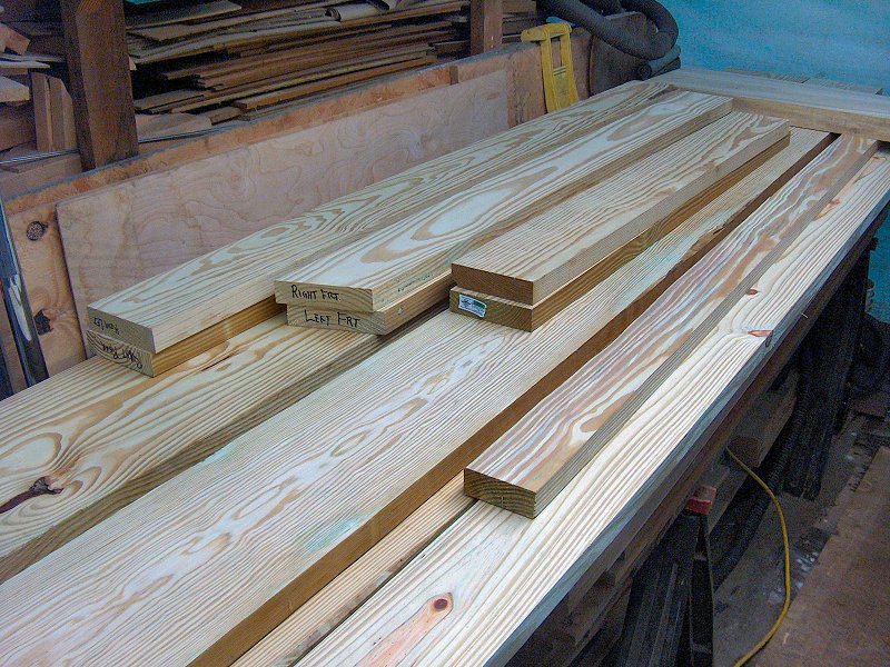
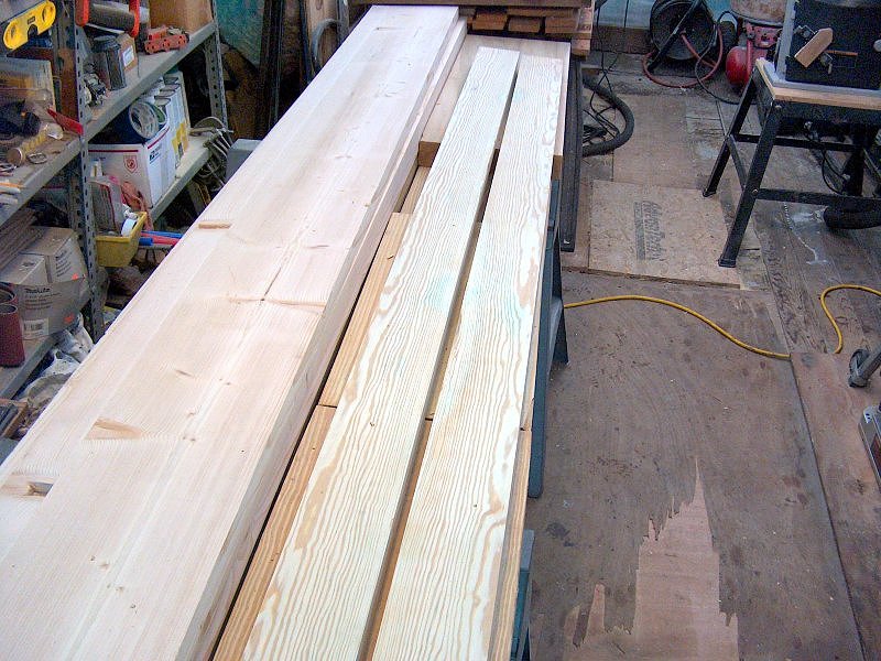
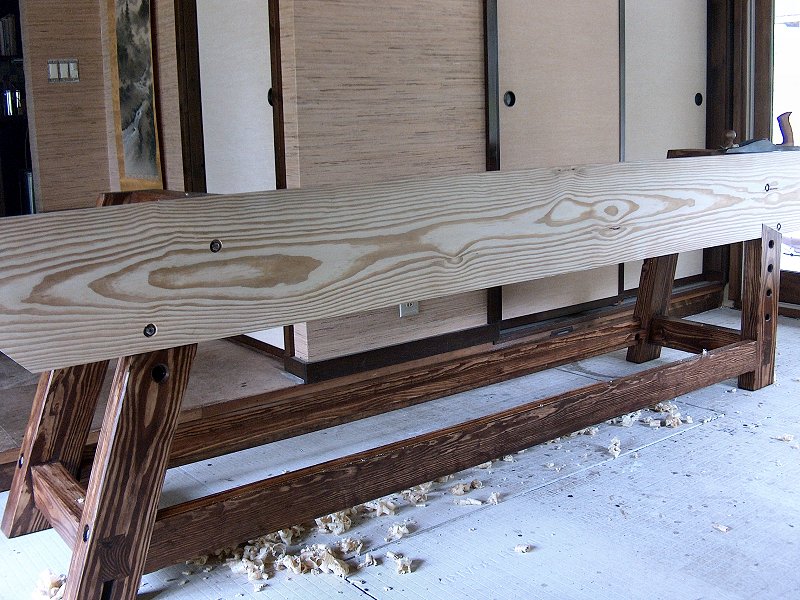
The faced and edged stock ready for assembly work (1 photo).
I purchased all of the pressure-treated stock I thought I'd require in August, which was one 2x4x10, five 2x6x10, one 2x10x12, and three 2x12x12, then stacked it all on edge in the shop and let it sit for a few months to dry out while I worked on other projects and bench plans. I don't have a moisture meter, but I could tell by the weight of the boards that it was getting to be time to start working on them by late-November. Ideally I'd hand plane all this stock to provide clean faces and edges, but without a proper bench and faced with the amount of lumber I had, I instead contacted a cabinetmaker friend of mine with some massive power tools and ran all the stock through his thickness planer and jointed an edge. He also picked up a massive 3 foot long chunk of 10/4 Poplar that I'll use for the leg vise chop and planing stop, and we ran that through the planer while we were at it.
The finished thickness of all the stock ended up being 1-3/8 inch, and with that dimension set I could then return to the plans and start working on the details of the leg assemblies (without knowing the finished dimensions, trying to get all the measurements figured out just doesn't work). I also purchased the five 2x10x10 pieces of Spruce that I'll need for the underside of the top and apron. With the Spruce stacked to dry and all the pressure-treated ready, I began working on the details of the leg assemblies.
Leg Cutting & Glue-up: early Winter 2014
With the 2x6 stock jointed on one edge and faced, I finalized the leg layout so I could start cutting stock and getting the leg
pieces glued together. Each leg is made from 2 pieces of 2x6 glued and screwed together, and I took some care to ensure I cut the
pieces from the same board when pairing up the chunks for assembly. That way if there was any cup on the board, the pieces would still
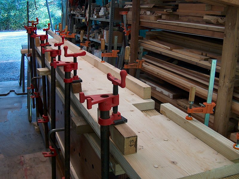
fit nicely, and all the grain would match up for finish planing. Each leg was glued and screwed together in the shop, then brought inside
to sit in the clamps overnight while the glue dried. I used Titebond® III Ultimate waterproof PVA glue, since
the thing is going to be kept in an outdoor plastic shed, and I like the longer open time of the III over their other PVAs.
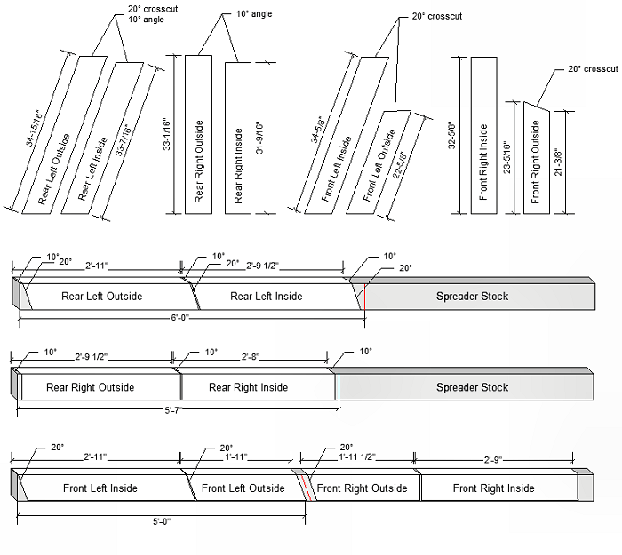
The plan for cutting the legs (1 image).
The layout and final dimension for the legs was fairly tricky, since each leg (other than the right front), has a couple angle cuts to deal with, and the stock dimensions were still not quite final. After an edge was jointed the stock was 5-9/16" wide or so, and after glue-up I ended up planing down the unfinished edge (along with a couple light passes on the original jointed edges) to give a finish width of 5-3/8". Everything had come back from the thickness planer at 1-7/16" thick, and the plan was to hand finish it down to 1-3/8" (2-3/4" actually, since almost every piece for the bench is made from double-thick stock that's glued and screwed together). One of each pair of leg pieces is longer than the other as well, so it will fit into a mortise in the top, or to create an oversize lap joint with the front apron.
Rather than try and measure everything then make perfect cuts, I just started with the rough cuts shown on the bottom part of the leg plan sheet then rigged together a layout jig so I could measure and mark the compound angle cuts accurately. The jig consisted of a 3-foot square chunk of plywood on the floor of the shop that was leveled with shims. I then clamped together a pair of angle cut leg pieces, and stood them on the plywood with the top end leaning against a sawhorse. I then put a piece of scrap 1-7/16" thick cut-off on the top leg angle cut, tweaked the leg to ensure the top was level, and clamped the whole thing in place against the sawhorse. The last step was to stand up a 3-foot steel rule, ensure it was plumb with a 2-foot level, mark the finished height of 34" on the temporary top piece, then mark off the offsets for the long leg height, and step off again for the short leg height. Like I said - fairly tricky, but I know the cuts are correct now. The measurements that ended up on the top part of the plans were taken from the finished legs (which is why they're a little odd), rather than attempting to work out the compound angle cut measurements first then cut to those lines. Scribing from marks on the actual stock always ends up being more accurate than trying to cut to measurements, it seems.
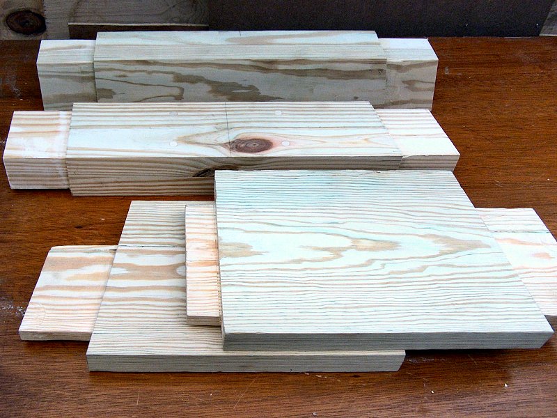
The Spruce stock faced, edged & glued-up (1 photo).
More Stock Prep - Mortise & Tenon Work: late Winter / early Spring 2015
I had managed to get all the leg pieces glued together before I crushed my finger at the end of 2014, but then the project was put on hold
for the rest of the Winter until I could get my hand working again after many weeks of physical therapy. It wasn't until March of 2015 that
I was given the go ahead to return to work, so that's where we pick up the bench project once more.
I had my Vanagon back from the shop at last as well, so the next step was to get the Spruce stock over to my friend's cabinet shop for thickness planing and edge jointing, then I got all that stock glued up to make the wide material that I'd use for adding thickness to the top pieces and aprons. With all the stock ready to go, I then glued together the double-thick bottom side stretchers, and cut the top side stretchers to length.
Next I started having fun with mortise and tenon joinery. As much as I would have enjoyed cutting all these joints by hand, since I didn't have a proper bench to hold my material while working it, I just went the power tool route and used the router to make the tenons. First I laid out the tenons by marking a line around the end of each stretcher (with about an extra 1/2 inch of length or so), then chiseled a little trough all the way around to ensure I could see the shoulder. I then used a Freud® 1-1/4 inch diameter flat-bottom "mortising" router bit, set for a 5/16 inch depth of cut, to waste away most of the material and define the sides of the tenon. The top and bottom shoulders of the top stretchers were then cut in with the band saw, while the bottom stretchers got the 5/16 inch cut on all four sides. All the tenons were then cleaned up by hand with chisels and a medium shoulder plane.
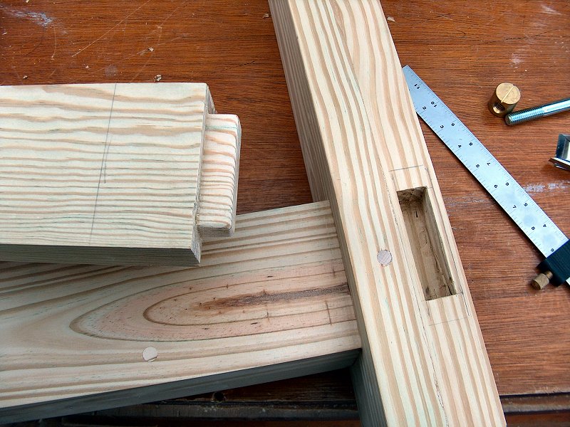
The mortises & tenons for leg assembly (4 photos).
With all the leg stretcher tenons done, I then turned my attention to cutting their mortises in each leg. As I'd done for the tenons, I again used a combination of power and hand tools to get the job done. I started with the top stretcher mortises, and cut those using the plunge router with the edge guide fence attached, and a 3/4-inch upcut spiral router bit (remember, the stretcher stock is 1-3/8 inch thick, and the 5/16-inch deep cuts on each face for the shoulder results in a 3/4-inch thick tenon). Because the top stretchers are set parallel to the legs, using the guide fence with the router ensures everything lines up correctly. After routing, a little clean-up by hand with a chisel for the corners and to get the top and bottom angles right, and the top stretcher mortises were good to go.
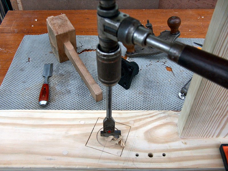
The bottom stretcher mortises were a little more challenging to get right, since those are not cut parallel to the legs. Rather than use the router, I went for a 1-inch self-feed bit in the power drill to get through the stock, then cut the rest out with the jig saw. I started with some careful measuring and marked the outline of the mortise with a chisel all the way around, then ran the drill bit in at each corner about half-way through the leg. I then flipped the leg over, and did the same thing from the other side. The leg mortises required a lot more hand clean-up work (a drill press with a Forstner bit would have made the initial holes much cleaner, but I don't have a drill press in the shop...), but the good news is these mortises are big enough that I could get inside them with the shoulder plane and everything cleaned up nicely with that.
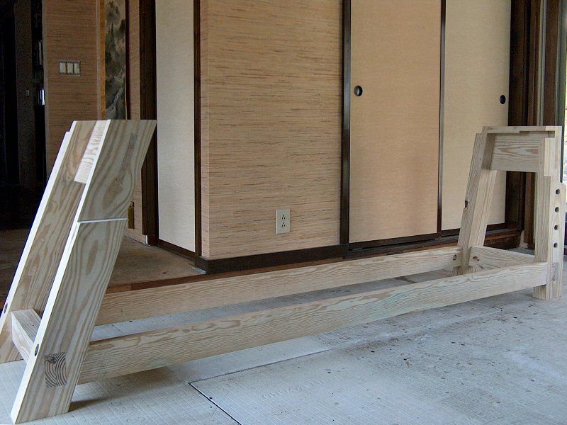
Leg Unit Assembly - Drawboring
Assembling the leg unit mortise and tenons was done using a technique called drawboring. Drawboring requires a little extra time to get right,
however the result is a very strong joint, and clamps are not needed for final assembly (which is nice for me since I have a few angled
surfaces to deal with). To create a drawbored joint, the mortise and tenon are assembled with a pin driven through the joint, however the hole
for the pin is offset on the tenon from the hole through the mortise. When the pin is driven through the assembled joint, it draws the
tenon shoulder tight up to the piece with the mortise, creating a strong mechanical joint that doesn't require glue.

Drawboring the leg assemblies (5 photos).
To begin assembly, I drilled a 3/8-inch hole through all the leg mortises for the pins. Each bottom stretcher mortise got one hole, and each top stretcher got two holes. I placed the hole about 3/4-inch back from the shoulder side of the joint, and bored it all the way through the leg. These holes are drilled without the stretcher tenons in place, although I did wedge a chunk of scrap into each mortise to prevent any tearout on the inner mortise walls while drilling. Next, the stretcher tenon is dry fit into the mortise, then the drill is inserted into the hole to mark the hole location on the tenon. The stretcher is then removed, and the tenon hole is drilled with a small offset toward the tenon shoulder. That's the part that gets a little fussy and requires some extra time.
I found that getting the point of the bit to move after marking the hole was a little dicey (the bit wanted to slide back into the marked spot, rather than bite into a new spot 1/16-inch closer to the shoulder), so I came up with a method that gave me a little more wiggle room to make the new hole in the tenon. When marking the hole location, I put the stretcher into the mortise, then added a couple thin shims to the shoulder and clamped the stretcher into position. I then put the auger bit into the mortise hole and gave it a little twist to mark the tenon from both sides of the leg. After removing the stretcher, I could then measure over a full 1/8 inch from the mark (the thickness of the shims, plus another 1/16-inch or so), and the drill bit would stay clear of the original mark. I drilled into the tenon from both sides to ensure the hole was correctly aligned, and the parts were ready for assembly.
The pins were cut from 3/8-inch Poplar dowel stock, and I sharpened the ends with a Stanley No. 22 dowel sharpener. Even though a drawbored joint doesn't require glue, I still added a little to the inner mortise walls, then slid in the tenons. I then pushed a 3/8-inch drawbore pin into the hole and wiggled it around a bit to help get things lined up, and finally drove the pins through to pull the leg assemblies together. I let them sit overnight for the glue to dry, then spent another day with the flush cut saw and belt sander getting everything cleaned up. Now it's time to add the stretchers to tie these leg assemblies together.
Bottom stretchers installed with bench bolts (1 image).
Stretchers & Bench Bolts: Spring 2015
The two bottom stretchers were ripped from a single 2 x 10 on my friend's table saw, then one edge jointed and each was planed to
4-1/4 inch by 1-3/8 thick. These bottom stretchers would get a shallow tenon into each leg, then get attached with
Veritas® Special Bench Bolts
![]() (1/2"-13 x 6") to allow for dis-assembly
if I ever need to move or store the bench.
(1/2"-13 x 6") to allow for dis-assembly
if I ever need to move or store the bench.
Once the stretchers were dimensioned, I then cut the tenons on the ends for the right leg first, since those fit into the leg at a right angle and would be a little simpler to lay out than the angled things on the left end. I want the front stretcher to be flush with the front of the legs (and front apron), but didn't have a lot of room to play since the outside of the leg would need a 1-1/4 inch countersunk hole for the washer under the through bolt. I decided to make the tenons 3-inches tall (5/8-inch shoulders top & bottom), then offset the shoulder from the outside a tad to give more room for that countersunk washer hole while still keeping the through bolt hole within the tenon by trimming off 5/16-inch for the outer shoulder and 3/16-inch for the inner, leaving myself a 7/8-inch wide tenon. The tenons were marked out and cut using the router, just as I'd done with the short leg stretchers, then the mortises were marked and cut into the legs using an auger bit for waste removal, and chisels for clean-up. I then took a couple shaves off each check of the tenon with the shoulder plane to ensure an easy fit into the leg mortises, and set about getting the bench bolts installed.
Bench Bolts Installation
Installing bench bolts sounds a lot easier than it is when dealing with 8-foot long stretchers, but the first thing to do is get the holes
for the bolts and washers into the outsides of the legs - that part isn't bad. Since I don't have a drill press available, I needed to come
up with a way to ensure the holes were straight through the legs. I came up with a "portable drill press" of sorts by using an upcut
spiral router bit in the router with the plunge base. That allowed me to get the hole started with a couple inches of depth that was straight,
then finish it with an auger bit in the hole started with the router.
First the hole location is carefully marked on the outside of the leg, then the router plunge base and fence is placed onto the leg. The router is fitted with the 1/2-inch upcut bit and put into the base with the tip of the bit just off the wood surface, then the whole works is tweaked to ensure the hole is aligned correctly and the router base is clamped into position. The router is then removed from the base and 1/2-inch bit is replaced with the 1-1/4 bit, which will be used to make the countersink for the washer. With plunge base the depth stop adjusted appropriately, the big bit is plunged into the leg to create the countersink. The router body is then removed from the base again and the bit swapped back to the 1/2-inch spiral upcut (but the base remains clamped in position). The router then goes back in the base, and the upcut bit is plunged into the leg as far as it will go to create the beginning of the through hole for the bolt. All the router stuff is then removed and things get interesting...
Bench bolt installation (9 photos).
In order to get the hole through the leg and into the stretcher in the right position, the stretcher needs to be installed in the leg and held
there, which is no small matter with an 8-foot long stretcher. I've seen some
right-angle carcass clamps![]() that may work
for this sort of thing, but I don't have any and didn't want to wait a week to get them, so I needed to come up with another way to clamp
those stretchers into position. After lots of fiddling around with blocking and F-clamps to hold the leg assembly to the bench, I clamped the
stretcher into position with a couple pipe clamps that were hooked to each other to get enough length and grab the end of the stretcher. I then
used the ratcheting bit brace to extend the bolt hole through the leg and into the stretcher as far as it would go. The stretcher was then removed
from the leg assembly, and I used the bit brace to bore into the stretcher until it bottomed out. I then fitted a 3/8-inch bit into the brace and used
it to try and clear all the chips out of the hole, then the stretcher was clamped back into the leg assembly to mark the location of the big brass nut.
that may work
for this sort of thing, but I don't have any and didn't want to wait a week to get them, so I needed to come up with another way to clamp
those stretchers into position. After lots of fiddling around with blocking and F-clamps to hold the leg assembly to the bench, I clamped the
stretcher into position with a couple pipe clamps that were hooked to each other to get enough length and grab the end of the stretcher. I then
used the ratcheting bit brace to extend the bolt hole through the leg and into the stretcher as far as it would go. The stretcher was then removed
from the leg assembly, and I used the bit brace to bore into the stretcher until it bottomed out. I then fitted a 3/8-inch bit into the brace and used
it to try and clear all the chips out of the hole, then the stretcher was clamped back into the leg assembly to mark the location of the big brass nut.
The 6-inch long through bolts that came with the Bench Bolt Kit weren't going to be long enough for my needs, so I replaced those with 8-inch stainless steel bolts from McMaster-Carr. I now needed to mark the location for their matching nut on the stretcher. Even with all the care given to try and get the through holes for the bottom stretchers nice and straight, they still end up being a little off so I find it's best to mark the location of the nut, rather than try to measure the location on the stretcher. To accomplish this, I made a little jig using a block of scrap wood with a couple lengths of 1/2-inch dowel sticking out of it (see photos). The dowel that goes into the leg hole is about 6-inches long, and the other dowel is about 10-inches long. The holes in the block for the dowel are carefully marked off the edge to ensure they're lined up, and they're then made with the upcut spiral bit and the router as before, to ensure they're straight. A bolt is then placed next to the long dowel, and allowing a little room for the countersunk hole, the center of the threaded portion is marked on the dowel. A little hole is drilled through the dowel at that mark, and a brad is inserted that will be used to mark the spreader nut location. With the spreader clamped in place again, the jig is then inserted into the leg hole, squared to the leg, and the brad is gently pushed onto the stretcher to mark the nut location. Everything is then dis-assembled, the hole is bored for the nut, and things are then re-assembled.
The stretcher mortise & tenons and bench bolt location for the left legs went along pretty much the same, with a couple minor alterations. To get the stretcher length correct, the location where the top of the stretcher contacts the leg is marked after carefully measuring from the right side top shoulder, then the left leg assembly is clamped into position against the stretcher and the angle for the left stretcher shoulder is marked into the stretcher. The tenon shoulders for the left end are also cut at an angle (the end of the stretcher is straight), so the top the tenon is a couple inches long, while the bottom only protrudes from the stretcher about 1/4-inch. This allows the stretchers to be attached to the right leg unit first during assembly, then brought up into the angle mortise of the left leg unit and bolted into position.

Top stretcher installation (11 images).
Top Stretcher Installation
The top rear stretcher is cut from a 2x4x8, then connected to the leg units with a modified half-lap dovetail joint and through bolted into
position. This top stretcher serves an important role in that it holds the two leg assemblies in place while assembling the bottom stretchers,
and also acts as a retainer for the bench top. Because it is installed against the back legs, it meets the top at a 10° angle and provides
a place underneath which the angled ends of the bench top cross-members will be held. The joints for the top stretcher were cut using the mortising
bit in the router as usual, then cleaned up with hand tools (see photos for details). The top stretcher is held in place using a single 3/8-inch
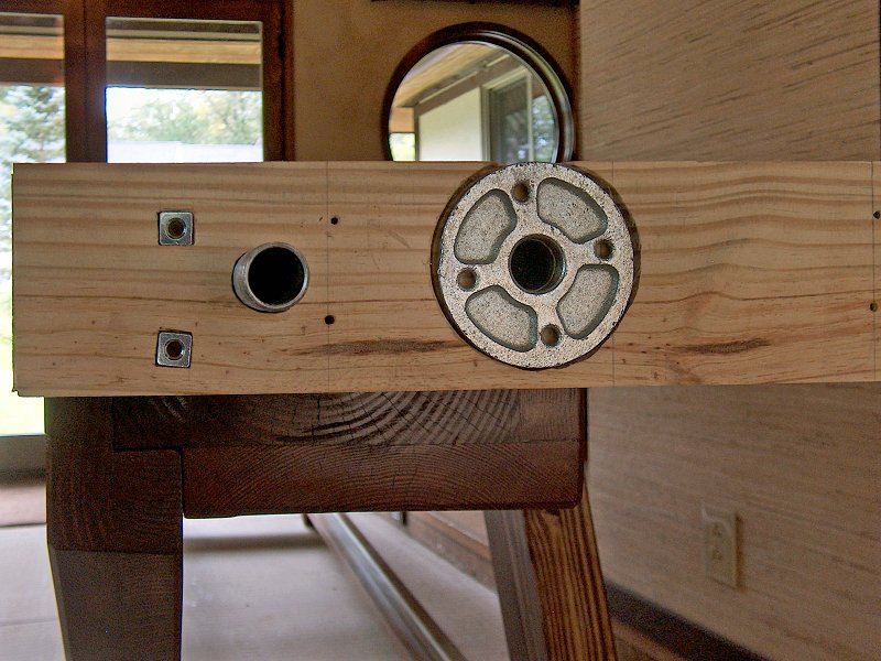
stainless steel bolt & washer at each leg unit, through bolted into a
threaded rod mounting plate![]() from
McMaster-Carr, mounted on the inside of the leg unit.
from
McMaster-Carr, mounted on the inside of the leg unit.
With the stretchers finished, the next step is to make any remaining holes for workholding fixtures in the leg units, get the shelf rails mounted to the two bottom stretchers, then apply the finish to all the base pieces so it can be assembled.
Mounting Assembly & Workholding Hardware in the Bench Base
Before applying stain and finish to the bench base assembly, I wanted to get all the holes made so I'd only need to stain everything once.
That meant I needed to get the hole locations for the leg and tail vise hardware figured out, cut the mortise for the leg vise parallel guide,
make the holes for the front apron mounting plates, and add additional dog holes to the right leg unit. I also needed to get the shelf supports
installed on the lower stretchers, and add a track for the sliding deadman to the front stretcher as well.
More leg work for workholding fixtures (8 photos).
I began with the apron mounting plates, using the method I'd come up with of using the plunge router with an upcut spiral bit as a "portable drill press" to ensure all the holes I made were straight. After getting two mounting plates installed for the apron on each leg unit, I turned my attention to the vise hardware. I opened the box for the leg vise screw to examine the threaded base, and realized that the thing is supposed to be mortised into the leg, and not just screwed on to the inner surface. I should have checked the base before assembling the leg unit, since it would have been a lot easier to get the hole made before the leg unit was assembled. It ended up going pretty well, since I still had enough room to get in there with the Stanley No. 984 short corner brace, fitted with an Irwin No. 22 expandable bit. I then had to make a decision about the parallel guide location and whether to put that above or below the side leg stretcher. I like the idea of keeping it low, so I made the 3/4-inch wide mortise for that just below the mortise for the leg stretcher. In order to have enough room for the thing, I made the mortise flush with the stretcher mortise on the outside of the leg, then plowed a groove in the bottom of the stretcher on the inside of the leg stretcher for the guide to ride in. I then moved to the right leg unit and the tail vise base, which was simply clamped into position, then holes for mounting bolts were drilled using the vise base as a guide.
Readying the Base Parts for Finish
With all the holes for base assembly and hardware done, I still needed to make the shelf rails and sliding deadman guide for the lower stretchers.
I cut a pair of rails to 1-1/2 inch square, then planed them down to 1-3/8 inch square to match the rest of the stock thickness. Each rail was clamped to
the stretcher, then I used a piece of 5/4 preassure-treated decking to determine the offset from the top of the stretcher for the shelf. I want a
little gap between the top of the stretcher and the tops of the shelves, so I added about 5/16-inch and marked the distance. The result puts the shelf
rail almost centered on the stretcher, which meant I also needed to bore some holes at each end of the shelf rails for clearance to insert the bench
bolt nut during assembly.
Final tweaks & finish on the bench base parts (6 photos).
The last piece needed for the base was a guide for the sliding deadman on top of the front stretcher. Because the deadman only runs part way across the front of the bench (there's 2-foot, 6-inches on the right that will be occupied by the tool storage box), I decided it would look better to add the guide to the stretcher, rather than mill away the stretcher and make it look oddly narrower on the right under the box. I ripped a piece of stock about an inch square, then took off the two top corners at 45° with the band saw to rough out the guide. I then planed smoothed one of the 45° faces, and attached the guide to the stretcher, offset a 1/4-inch from the face, with plugged screws and glue. The offset was added so the sliding deadman base will have a small square edge at the front, rather than a fragile point. After the glue dried overnight, I then belt sanded and planed the angle on the back of the guide until it was flush with the back face of the stretcher.
The last step prior to finish application was to go over all the base parts and ease the corners of everything with the 45° guided chamfer bit in the router. I didn't want the chamfer to just disappear where parts met, so I marked an offset of one inch wherever two pieces joined each other. This offset would leave a flush or square transition, and I think it adds a nice detail. I also had a piece of stock left over from the shelf rails, so I decided to add an extra crossbar inside the left leg assembly that is installed so it is at the same height as the top of the tool storage box (flush with the bottom of the front apron). This will provide a place to hang F-clamps, or store long stock beneath the bench top. The crossbar and shelf rails were given their edge chamfer prior to assembly, then I went over all the edges of the stretchers and leg units with the router. I also took the extra few minutes to finish the end of each chamfer with a bullnose shoulder plane and chisel to give a crisp, stopped chamfer, rather than the rounded end left by the router bit. I then screwed and glued the shelf rails and crossbar into position, gave everything a final wipe down with mineral spirits to remove layout lines, then hand sanded all surfaces with 150 grit paper to ready the parts before ragging on a coat of Minwax® Wood Finish™, English Chestnut 233, oil-based wood stain. After two coats of stain, everything then received a couple coats of Minwax® Tung Oil Finish to add a little lustre.
Details of working the front apron (6 photos).
Working the Front Apron: late Spring 2015
After a few days of finish application in the shop, I brought all the parts inside so I could assemble the base on a level floor and start
work on the front apron. The first thing to do was get the half-dovetail lap joint cut into the apron for the right leg, then I clamped the
apron into position against the base assembly. With all the bolts for the base assembly loose, I then did a lot of careful measuring and tweaking
to get the right leg (which determines how the tail vise will align with the top and apron) aligned and square with the apron. With everything lined up
nicely and clamped, I marked the holes for the front apron bolt holes by inserting a brad point bit though the hole in the leg (with the mounting
plates removed). I then took the apron back to the shop, bored the bolt holes using the 3/8" upcut router bit, then installed the mounting plates on the
legs and bolted the apron in place to check the fit. The apron had been cut a little oversize in width and length, so now that it was bolted in place
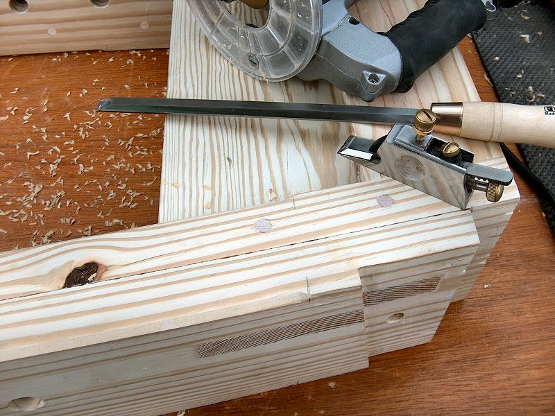
I could make the final marks for length and return it to the shop for final dimensioning. I cut it to length, then hand planed it smooth to remove about
1/16" of material and knocked off a couple 45° cuts on the outside bottom corners. I then bolted it back into place and jointed the top edge
even with the tops of the legs.
With the front apron cut to finished size and fitted in place, I then spent some time with the plans open on the computer and marked all the locations for the twenty five front dog holes. Because I'll glue and screw a second board to the back of the apron to increase thickness, I want to have all the dog holes laid out first to ensure I don't end up with any assembly screws in a dog hole location. I also marked the location for some additional through bolts that will connect the apron and top together, as well as a couple bolts that will hold the tail vise frame in place. Once I had double checked all the hole locations, I then removed the apron and took it back to the shop for lots of hole making.
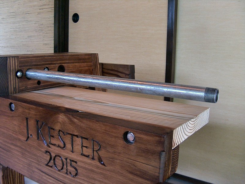
The first step to "perforating" the front apron was to use a 3/4-inch auger bit in the hand brace and give a couple turns at each hole location to mark the hole diameter in the apron. Then it was back to the "portable drill press" plunge router set-up with the 3/4-inch upcut spiral bit and fence to bore all the holes through the apron. After lots of clamping and tweaking all the holes were done. I then made the 1/2-inch deep counterbores for the assembly bolt heads and washers with a 7/8-inch auger bit, and finished the through holes for the bolts with a 9/16-inch bit. Next, I flipped the apron and routed out a 2-1/4 wide, 7/16-inch deep dado for the planing stop block that fits into the apron just past the leg vise on the left end. Because I want the planing stop to align with the dog holes and tail vise in the top, it's located fairly close to the front of the bench, and the apron needed to have a little material removed to ensure everything lines up correctly. I also routed a 1/2-inch wide, 3/4-inch deep rabbet along the lower inside edge of the apron that will form one half of the 1-inch wide groove to house the top of the sliding deadman (the other half will be a rabbit in the back board for the front apron). I also noticed a split in the far left end that worried me a little, so I added a butterfly/dovetail key to help control that. The last thing to do before adding the backer board is to carve in my name and date on the right end of the apron below the tail vise location, but that will have to wait a couple weeks for my hand to recover from the second surgery to repair my flexor tendon.
More front apron work (9 photos).
The Front Apron Backer Board
With the incision from my second surgery healing nicely, I was able to get back to the woodshop near the end of May and take care of more work on
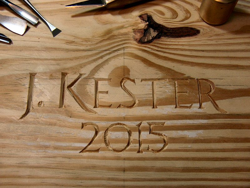
the front apron. Before gluing the backer board in place, I did some incised letter carving on the right end of the apron and added my name and date
to the bench. This was my first attempt to letter carve, so I spent less than twenty bucks on a set of tools from China (on E-Bay) to just try it out.
I also picked up a nice fishtail chisel from Lie-Nielsen for getting into the seriffs (and to use for dovetail work later on). I laid out the lettering
on the computer then printed a full-size image of what I wanted. I then spray mounted that sheet to the apron, and cut the outline and center-line for
all the letters into the bench. Once everything was marked out I removed the template, and carved out the rest of the letters. For a first attempt, I'm
quite pleased with the results.
Next I turned my attention to the front apron backer board. This piece would add mass to the bench, provide the thickness to the apron for holdfast and planing stop use, and create the other half of the track for the top of the sliding deadman. I cut the 1/2-inch by 3/4-inch rabbet for the deadman first, then added a notch to the right end of the groove to create a location to remove the deadman from the bench. It seems the "normal" way to make the deadman removable is to make the groove deeper than the tenon on the top of the deadman and leave an extra inch or so of clearance between the upper groove and shoulder on the deadman, then lift the deadman into the groove and swing the bottom off the lower track. I didn't like the idea of having all that extra space above the deadman, so I decided to make a spot at the top right end where there was room to swing the top back out of the track, yet keep the deadman captive for the rest of the track length without all that slop at the top. I made a little gizmo (see photos) for the back of the backer board that I could pivot out of the way to remove the deadman, but in use it would keep the deadman in place so the thing never accidently falls out of the track.
To get all the backer pieces attached in the correct location, I then clamped a long strip of scrap to the apron (along with another piece of scrap to the front so I didn't leave clamp marks on the apron) that was the same thickness as the top backer board - the way this thing fits together is the top backer board sits on top of the apron backer board, and the top sits on top of the apron, so I needed this spacer to get the stair-step arrangement of everything properly aligned. I then added the backer piece for the left end of the apron that fits fromt the end to the plaing stop slot, and another backer piece between the planing stop and the left leg. Those two pieces were glued and screwed in place, then I set about marking the long apron backer with all the locations of the top dog holes and front through holes so I wouldn't put any screws into a hole location during assembly. With everything carefully measured and marked, I gave the apron and backer a healthy coat of glue, clamped them together, and screwed the whole works together with a screw every few inches. After the glue cured overnight, I then scraped and belt sanded the back, planed all the edges, and sanded the front to ready the apron for finish application.
The tail vise frame (9 photos).
The Tail Vise Frame: early Summer 2015
After a few coats of finish to the front apron piece, all parts were brought inside so I could assembly the bench once more on a level floor
and start working on the tail vise. Over the course of building the base frame and front apron, I'd given a lot of thought to how exactly this pipe
vise unit I'd decided to use was going to function (or not). My original idea was to use the pipe vise so the tail vise would work both as a
"standard" tail vise with at least 12-inches of travel, but then also allow the option to extend it out a few feet to hold 10 or
12-foot stock when needed. The plan was to use a pair of 3/4-inch pipes (one for the clamp mechanism and one to act as a guide bar) that would
rest against the bottom of the bench top so when extending the tail vise jaw, the pipes will prevent it from sagging and flopping around. As I worked
through the details of how this was actually going to function, it became clear that I would need a lot of blocking under the right end of the bench
to support all this stuff. I ended up building a fairly massive vise frame unit that gets attached to the bench assembly after the apron and legs
are assembled.
Before applying finish to the front apron, I had cut a notch out of the right end above my name to accommodate the tail vise jaw unit. I then set about making the front part of the jaw unit using a piece of offcut from the original front apron stock so the grain would match nicely yet the piece would have the extra length to attach the end of the jaw unit. This piece was then glued and screwed to additional stock to create a roughly 4 by 4-inch front jaw that will have a few dog holes in it, and a sliding dovetail to act as a guide. This front part of the jaw would also sit on the vise frame shelf that gets attached to the apron and upper leg assembly cross-member with a few 3/8-inch knock-down fasteners. The sliding dovetail of the jaw piece then fits into a matching dovetail that is attached to the shelf frame. The shelf frame dovetail piece also acts as a guide for the main vise clamp pipe, which meant it needed a 1-inch diameter hole through the length of the piece. Rather than attempt to drill an 18-inch long hole, I made the guide piece from two pieces of stock with cove cut in them with a 1/2-inch deep by 1-inch diameter router bit. I then cut the sliding dovetail in one of the pieces, then glued and screwed the two pieces together to create the guide block.
With the shelf and front jaw guide fitted, I started work on the rest of the frame that would house the guide bar for the vise jaw. My original idea was to built a sort of box from dimensional lumber with a flat face at the end, and couple cross-members spanning the frame shelf to support the top and the guide bar. The more I delayed in making the thing, the more I became convinced that wasn't really going to work. Instead, I ended up laminating a solid block that fills the entire area between the front half of the bench top and the tail vise shelf. I laminated together another couple pieces of stock with a 1/2-inch by 1-inch cove to form the long guide bar hole, and also ripped a couple of the pieces so they would form a hole in the top of the vise frame that would accept a block that's attached to the bottom of the bench top to help align everything. Please see the photos to help make sense of what I'm attempting to describe.
The tail vise jaws (6 photos).
The Tail Vise Jaws
While getting finish applied to the tail vice frame unit, I moved on to creating the tail vise jaws. The front jaw stock with the sliding
dovetail was ready for more work since I'd needed that to get the frame aligned, but I still needed to get the end jaw built. This piece was
going to be rather tricky as it needed to house the base for the guide bar, and also hold a couple captive nuts to secure the tail vise pipe clamp
head. I wanted to use a nice dovetail joint to join the two jaw pieces together, but I didn't want to try to work on that joint while the end
jaw had a five-foot long pipe sticking out of it. I decided to first temporarily screw together two of the three pieces of end jaw stock and use
that chunk to get the guide bar base fitted, then I could attach the base to the third piece of stock and screw that piece on to have a finished
jaw piece on which to layout and cut the dovetail. Once the dovetail was ready for assembly, I could then remove the screws and attach the guide bar,
then glue and screw the end jaw back together while assembling the dovetail joint with the front jaw.
Rather than go into all the detail here of creating the dovetail joint for the end jaw, I recommend the article
How to Make 'Condor Tails'
![]() by Jameel Abraham of Benchcrafted. The article
provides excellent step by step instructions and photos for creating the joint, and is also available as a PDF through the link provided.
by Jameel Abraham of Benchcrafted. The article
provides excellent step by step instructions and photos for creating the joint, and is also available as a PDF through the link provided.
With the end jaw pieces cut a little oversize and the dovetail complete, I then glued each piece to the front jaw over the course of a couple days. The first piece went in without any difficulty, then the inside of the second piece needed to have a section cut out to house the threaded base of the vise guide bar before it could be glued into position. After a lot of test fitting to ensure the guide bar didn't bind within the frame and with the pipe securely screwed into the base, I marked the location of the guide bar base on the jaw, and took everything back to the shop to assemble the second piece with the guide bar in place. After the glue cured overnight, I then added the outer end jaw piece with glue and screws through the whole works, and again let the glue cure overnight. After a bit of clean up with the block plane and belt sander, the tail vise jaw was mostly complete - the top piece of the jaw will have to wait until the bench top is done so it can be planed flush to the top.
Detail plan for the bench top holes & screws (1 sheet).
The Bench Top: mid-Summer 2015
I planned to make the bench top from a double thickness of stock to provide mass and adequate thickness for holdfasts, just as I'd done with the
front apron. I had also taken some care to attempt to make the top so it will stay in place without and fasteners visible on the bench top - there
were some fasteners along the front that connect the top to the apron, but nothing planned between the top and the legs. The idea was that the top
would be a loose fit into the base assembly with cut outs in the backer board to fit around the tops of the legs. The apron bolts will prevent it from
moving around and keep the front edge in line, but as the top expands and contracts it will be free to move as needed along the width of the boards.
The top and backer boards are glued and screwed together just as the front apron boards are, but the cross-members that hold the two top boards together
would only be fastened with screws to allow for seasonal movement. It all seemed like a good idea - we'll see how it works out...
The first step for assembly was to cut the backer board for the front board to size so it would fit between the leg cross-members. This didn't have to be a perfect fit, since I wanted to allow for movement and ensure I could lift place the finished top in position without binding. I laid the backer board in position then simply traced the outline for the tops of the legs onto it and made the cuts. I also marked the position of the two front connection knock-down fasteners, then drilled the holes in the top for the round brass retainer nuts. These holes did not go all the way through the backer board - I only made them deep enough for the threads to catch, then with the backer board clamped into position I put a liberal squirt of silicone into the nut hole and snugged up the bolts. The silicone will hold the nuts in place during assembly, but also allow a little bit of movement for expansion and adjustment if needed.
With the center backer board cut to length (and left a little wide at the back), I then went back to the drawing board and spent some time working out the exact location for all the bench dog and holdfast holes, as well as the cross-members. Before I glue and screw the top laminates together, I want to be sure I don't end up with a screw interfering with a hole position later on. The front dog holes are spaced 4-inches apart, so for the front edge I just centered a screw between each dog hole. For the rest of the bench top, I laid out the holdfast holes based on the diameter of the coverage of the holdfast arm (which is about 13-inches). With a little tweaking a worked out that I could put another screw every 6-inches down the center of the top board, and then at the same spacing along the back edge of the board. See the plan sheet above for details.
Working on the front top laminate (8 photos).
Assembling the Front Top Laminate
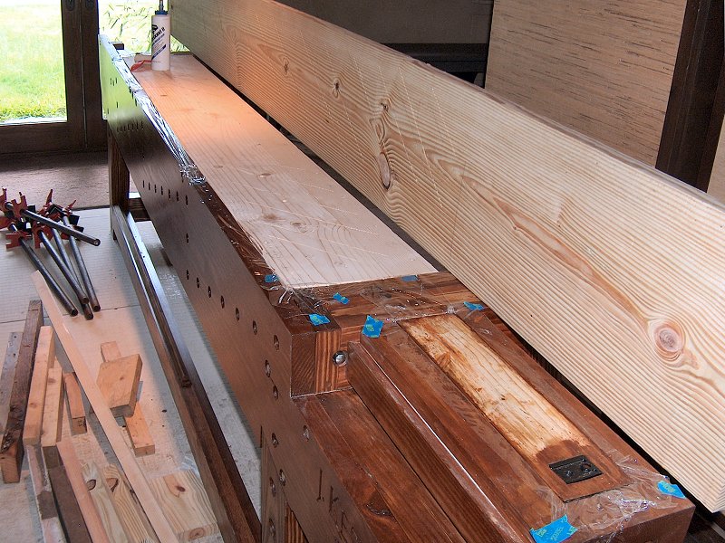
I wanted to make the lamination with everything in position, rather than glue the boards together in the shop then have to trim them to fit between
the legs afterward. I pre-drilled and countersunk all the fastener location in the backer board, then placed the backer board in position within
the base assembly and laid the top board in position to do a final test fit. I noticed the top and backer board both had a little twist to them,
so I "cheated" a little and made a series of shallow cuts with the circular saw in each board, perpendicular to the twist and avoiding
any hole locations, to relive the tension and allow the boards to easily clamp flat during assembly.
To ensure the whole thing would fit easily, I placed a bunch of 1/16-inch thick cardstock shims along the top edge and both ends of the backer board before bolting it into position. The shims made the backer board stick up just a little above the edge of the apron so there would be good contact when clamping, and also made certain the backer board was centered between the legs. I then lined all the edges of the leg assembly with plastic wrap so any glue squeeze out during clamping wouldn't stick to the leg assemblies. The front edge of the top board was positioned so there was a slight overhang at the front apron (which will be planed flush later), and the back edge (which had been jointed square long ago at my friend's shop) was just shy of the edge of the backer board (so the backer board can be planed even with the top after assembly). Both ends were a little long, so those will be trimmed to fit after the glue's set. Satisfied with the fit and position, I then flipped the top board and gave all contact surfaces a generous coat of Titebond® II Extend Wood Glue with a small roller, then put the top back in position and clamped everything together. As soon as the clamps were in place, I then put in all the screws I had access to (the front edge was blocked by the apron), and let the whole thing cure overnight.
Next I brought the top assembly back to the shop and cleaned up all the edges and removed any glue squeeze out, then put in any screws I didn't have access to during clamping and installed plugs in all the screw holes. While the plug glue was drying, I set to work on the backer board that fits at the end with the planing stop. The stock was cut a bit undersize, then the top was placed back on the bench and the backer board clamped in position to get marked for the planing stop cut out. After marking the backer board, the planing stop opening was cut out with a jig saw and cleaned up with rasps and sandpaper for a good fit. Back to the bench with the backer board, and the top was now marked for the planing stop. The top was then taken back to the shop, and I created a planing stop cut out pattern with a piece of scrap 1/4-inch plywood. After ensuring the planing stop block fit easily through the ply, I then screwed the plywood to the bench (the holes won't be seen when the top is laminated), aligning it with the marks from earlier, then used a top bearing flush cut router bit (the one I'd used to cut the "condor tails") to cut the opening for the stop block. After a little clean up with a corner chisel the top and backer board end piece were glued together at the bench.
Working on the top cross-members (4 photos).
Installing Top Cross-Members
The last work on the front part of the bench top was to make and install the seven cross-members that hold the two section of the split top
assembly together. These were milled to 1-3/8 inch by 2-inch by about 15-inches long. I then removed all the shims and plastic from the bench top
and bolted the top into position. I laid out and marked where each cross-member went on the bottom of the bench top, then measured the distance to the
rear top stretcher to get the proper length for the angled end of each cross-member (less a 1/16-inch on each end so ensure I can sit the top into
position when assembling the bench). With all the pieces cut, I then laid out where the connection screws would go (three in the front half, and two
for the rear). and pulled out the router.
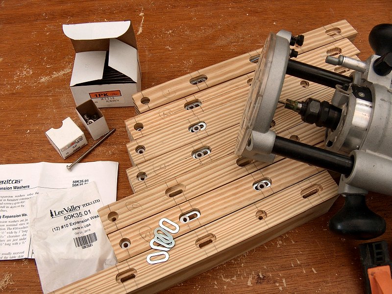
The cross-member connections are a little tricky, since just screwing and gluing these things to the bench top isn't really an option - the top is going to want to expand and contract across its width, so my goal is to try and keep the front edge flush, and have any expansion take place toward the rear. To try and accomplish that, the front-most screw for each cross-member is installed with a straight hole and a little glue, but the other screws are installed through elongated holes with no glue and the special Veritas® expansion washers. To make the holes for these, I started with the 3/16-inch upcut spiral bit and cut all the slots on the exit side of the cross-members first. I then switched to the special Veritas® screw slot router bit, and cut the 1/2-inch diameter counter sunk slots for the head side of the screws. I then relieved the edges of the bottoms of the cross-members with the chamfer bit, sanded them a little to ease any sharp bits, and installed the cross-members with just the one front screw and a little glue on the first 2-inches or so. Once the glue is dried for these things, I think it'll finally be time to get the bench into the wood shop before attempting to get any more work done on it.
Completing the bench top assembly (5 photos).
Completing the Bench Assembly: late-Summer 2015
I spent a few days working on getting the shop ready for the new bench by taking apart the old sawhorse lumber-stack / bench mess, then making a new
wood storage rack along the wall so I would have a good open area to locate the new bench. I then partially dis-assembled the bench (I kept most of
the base unit bolted together), and re-located the whole thing into the wood shop. After a lot of shimming under three of the legs to account for the
very uneven floor surface, I was ready to get back to building the rest of the bench.
With the bench in the shop, I next got to work on the rear section of the top laminate. I first did some measuring to make the appropriate cut-outs in the bottom Spruce piece to fit around the tops of the leg assemblies, then coated both pieces with plenty of Titebond® II Extend Wood Glue with a roller and clamped everything together. It was sure nice working on the partially built bench - nice and solid with plenty of area to work!
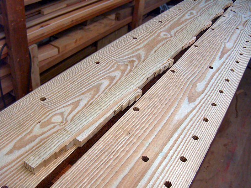
After the glue cured I then set aside the rear half of the top and laid out all the dog and holdfast holes for the front half of the top. I figured it would be a lot more convenient to get all these holes started with the plunge router while the two bench halves were separate so I could get at the edges of each half with the router guide fence. I carefully measured the hole locations according to the plan sheet above, then started each hole with the 3/4-inch auger bit, and followed that with 3/4-inch upcut spiral bit in the plunge router. Once all the holes were plunged for the front half, I then put the rear half on the bench and did the same thing to get all those holes made. With all the holes in place, I was finally ready to get the two halves of the bench top put together.

The finished bench base unit (1 photo).
Putting the two halves of the bench top together was fairly easy - I assembled the thing upside-down on the bench frame with just a dab of glue on each of the cross-members (that were already attached to the front half), and placed a bunch of short pieces of 5/4 lumber between the two halves to ensure I'd have plenty of room between the two halves for the center planing stop / filler strip that gets installed later. With the 5/4 spacers in place, I did a good bit of clamping to keep the two halves in line, as well as a few clamps between the top pieces and the base assembly to make the thing flat. With everything clamped in place, I drove the 2-1/2 inch long screws through the cross-members (that extra work time provided by the Titebond® II Extend sure is nice), and the top was assembled. After the glue cured, I then trimmed the ends flush and cleaned off the screw plugs along the bottom, and applied a couple coats of stain to everything before I flipped it over and bolted it into position. See the photos above right for details. With the top bolted in place, I then spent an hour or so with the No. 6 Stanley plane and flattened the whole thing, then followed that with a few coats of stain and oil finish. With that, the bench base was completed!
Workholding Fixtures & Vises
The leg vise chop and workholding fixtures plans (1 image).
The bench base and top was assembled, however the bench wasn't ready for use yet, as I still had many workholding fixtures to create as well as get the vise chops made so I could hold my workpieces. I also still needed to make the bottom shelf pieces and tool storage unit. Still plenty to do...
The Center Planing Stop Strip: early-Fall 2015
I actually need to backtrack a little regarding how I put the bench together now, since I made the center planing stop strip prior to applying
the finish to the assembled bench. I wanted to get the top of the center strip planed even with the bench top while I was flattening the top,
and that had to happen before getting finish applied. The center stop was a little complicated as well, since rather than making the typical
strip with notches in it for the cross-members that I flipped over when I wanted to transverse plane some stock, I decided to make something that
I could set at various heights depending upon the thickness of the stock on which I intend to work. This required a good deal of planning to
come up with something that would work and wasn't too difficult to make (see the plan sheet at right for details).
I figured the easiest way to accomplish this would be to create a plain insert of the same width for the entire length (except of for the ends), then add a series of small stepped blocks that would allow me to raise the strip to a variety of heights and have those steps rest on the cross-members. I also wanted the center strip to have some slots at the ends to serve as a place to insert a marking gauge, chisel, or saw, and also not have the center strip stick out the ends of the bench when using it for transverse planing. I decided to make the end pieces (from each leg assembly outward to the ends of the bench) separate from the center planing stop and use those as slotted tool storage. The left end piece needed to be stepped as well, so the center piece would rest on it when in use. That also meant I needed a small filler block at the junction between the center and left end. As I said, a little complicated, but it seems to have worked our pretty well.
The center planing stop construction (10 photos).
To make the stepped blocks, I cross-cut the step depths into a couple pieces of scrap two by six, then milled out the step with the router. Once the steps were formed, I then sliced the stock into 1-inch wide blocks. This method ensured all the steps were the same depth (about 3/16 inch). The steps were then glued to the main strip with the strip in place in the slot, and each step butted up against a cross-member. For the two end pieces, I planed some stock down to 1/2-inch thick and 1/4-inch thick, then sandwiched the 1/2-inch pieces between the 1/4-inch pieces to make the tool slots. Once the glue for those pieces was dry, I then cut the ends to the proper profile. With all the pieces assembled I sanded the sides and bottom a little, then placed everything into the bench and planed the top flush with the bench top. The completed piece can be set at 3/16-inch, 3/8-inch, and 7/16-inch heights for working with 1/4-inch, 1/2-inch, or 3/4-inch stock. See the photos at left for more details.
Bench Top Planing Stops & Dowel Former
In addition to the center planing stop strip, I also had a few
other chores to attend to before applying finish to the bench top. I had already done much of the work for the installation of the planing block
in the left end of the bench, however I had planned to have that block align with a small Lee Valley pop-up bench stop to facilitate working
on large panels. I also had a Veritas® Dowel Former that I thought would work well down at the left end of the bench.
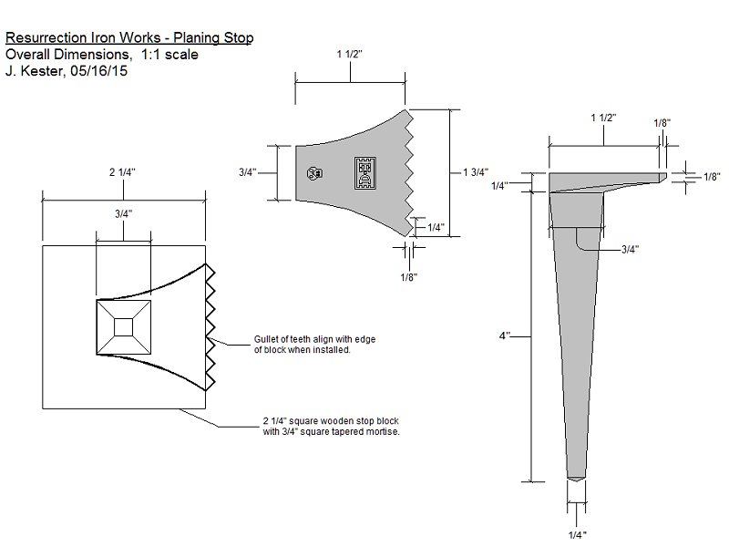
The planing stop plans and installation (9 photos).
The first item I addressed was the planing stop block. I had contacted a number of blacksmiths back in May to determine who was willing and
able to create the toothed planing stop I was looking to install. Based on the bloggers recommendations below, I first tried Peter Ross, but he never responded.
I also tried Mark Atchison, who eventually responded, but only after a couple months and I already had the stop made by someone else. The guy
that finally came through was Derek Heidemann of Resurrection Iron Works
![]() , in Millbury, Mass. When I contacted him,
he responded immediately. I whipped up a quick plan sheet, and he delivered the item less than a week after receiving the plans. How these
guys can make stuff this nice for $65, I'll never know, but thank you Derek! After having the thing kicking around for many months, I was
ready to install it at last.
, in Millbury, Mass. When I contacted him,
he responded immediately. I whipped up a quick plan sheet, and he delivered the item less than a week after receiving the plans. How these
guys can make stuff this nice for $65, I'll never know, but thank you Derek! After having the thing kicking around for many months, I was
ready to install it at last.
The traditional method of fitting the planing stop block into the bench is to create a large mortise then friction fit the block into the hole. Because my bench is basically stored outside, I wanted to have a little better control over how the block fits, rather than have it too tight in the humid Summer, then just fall out of the bench in the dry Winter. The hole in the bench top is cut slightly oversize to ensure the block will fit (addressed above in the Assembling the Front Laminate photos), but below the bench top where the mortise extends through the front apron, I added a block to the back of the apron with the other half of the mortise that's attached with screws and leather lined. This block allows me to adjust the fit of the stop block as needed, and the leather lining holds the block in place while still allowing easy depth adjustment. I also dealt with the concern regarding the teeth of the planing stop sitting above the bench all the time by making it so I can simply pull the block up out of the bench, then flip it over and insert it from the bottom to store it with the toothed bit under the bench. As usual, please see the photos above right for more details of the planing stop installation.

Completing the tail vise assembly and installation (9 photos).
Tail Vise Assembly: Fall 2015
I discussed most of the tail vise jaw construction above in the
Tail Vise Jaw construction section, however I had only done enough work to get the tail vise frame fitted with the
front apron and bench top. With the bench top now installed (but again, before I actually applied the finish), I needed to add the top piece
to the tail vise jaw so I could plane it flush with the bench top before applying the finish to both the top and the tail vise jaw. The top piece
was cut slightly oversize, then simply glued into position with lots of clamps and glue. After the glue was set, I then cleaned up all the edges
using a flush trim router bit on the end grain, and a hand plane on the sides (see photos at left). With the tail vise jaw sized, it was then fit
into the bench and I planed the top even with the bench top.
Now I needed to get this pipe vise mechanism working by tuning the jaw fit, and I could finally get some finish applied to the whole thing. Easier said than done... while I'm satisfied with the pipe vise function, getting the thing to work as I wanted turned out to be a bit more involved than I would have liked. If I had to do it again, I think I would have just installed a Veritas® Quick Release Tail Vise and been done with it. Sure, it's $300, but considering the time I've been fiddling with this pipe vise thing, I'd have been okay with that. The first problem I faced was getting the thing to open... my original plan was that I could just turn the handle to open it a few inches, then reach inside to depress the release button and slide it out to whatever distance I wanted. The trouble was that the pipe vise base grabs the pipe such that it only prevents it from coming out of the bench, but not from sliding into the bench. So, when I turned the end handle, rather than opening the vise, it simply pushes the pipe the handle is attached to further into the bench. It became clear why they had designed the thing with the ability to add a foot pedal, and that I was going to need to add one to get the thing to work.
I dug through the scrap heap and found a couple pieces of stock that would work for the pedal mechanism, and after a visit to the local hardware store I came up with a small chain and a couple of pulley sheaves that I installed to guide the chain from the vise base down to where I decided to place the pedal (rope stretches - chain doesn't). I had an old metal "Stud Step" thing kicking around, so after a little time with the Sawzall and grinder, I'd fabricated a respectable looking pedal mechanism. I installed the unit below the shelf supports on the stretchers, and it worked out that the chain will clear the tool box without difficulty, routed down behind the right leg. The tail vise jaw still sticks during some of its travel so a little more light planing will be needed, but it seems to be working well enough. After finish application, I also installed the six Veritas® Prairie Dogs in the jaw dog holes, which work very well while staying in place to prevent debris from collecting in those blind dog holes.
Leg vise & parallel guide preparation (12 photos).
Leg Vise Assembly: Late Fall 2015
The leg vise chop was cut from a hefty chunk of Poplar,
based on plan shown above. I decided to keep the outline simple to match the rest of the appearance of the bench, rather than add the curved outline
that seems so popular on many benches being built these days. Cutting the chop was nothing special, although I did clamp it to the bench and trace
the outline of the leg to ensure everything would line up, rather than try and measure it based on the plans.
One issue I had to deal with was that I had a 36-inch piece of 10/4 Poplar to work from, and because of the 20° angle of the leg, that wasn't going to be long enough. The good news is that because I would be adding a small block to the bottom to meet the length requirement, I could cut the mortise for the parallel guide on the band saw, rather than have to chop the thing out with a chisel. Once the outline for the main part of the chop was cut, I then did some clean up on it, and clamped it back to the bench to mark the mortise location for the parallel guide. With the mortise outline marked, I then got to work on the parallel guide. Rather than cut the mortise for the guide in the chop now, I wanted to get the tenon cut in the guide bar so I could use it accurately mark the size to the mortise from the tenon based on the marked mortise location, rather than try to measure it.
The parallel guide was made from two pieces of 1/2-inch Poplar laminated together, then planed down to 3/4-inch thick. I hoped by using a couple pieces of thin, laminated stock, I could counteract any warp or twist that might develop later, and also reduce the likelihood of the thing splitting under the tremendous pressure that's put on the guide bar holes when in use. With the parallel guide stock planed smooth and nicely fit to the mortise of the leg, I then marked it to length (leaving about 1/2-inch extra length for the tenon through the vise chop), and cut the tenon in the end using a chisel to mark the shoulders and the Stanley No. 71 router plane to clean up the cheeks. I was only taking off 1/16-inch per face, so this went very quickly with the No. 71. I could now trace the tenon onto the main piece of the vise chop, and cut the top half of the mortise with the band saw. I then cut the bottom half of the mortise into the vise chop extension piece, screwed the two pieces together and did a little chisel clean-up for a snug fit. I then re-assembled the chop with screws and plenty of glue. The next day I then trimmed the bottom of the chop to shape and did some final clean-up with the smoothing plane. The next step was to get the screw handle mounted.

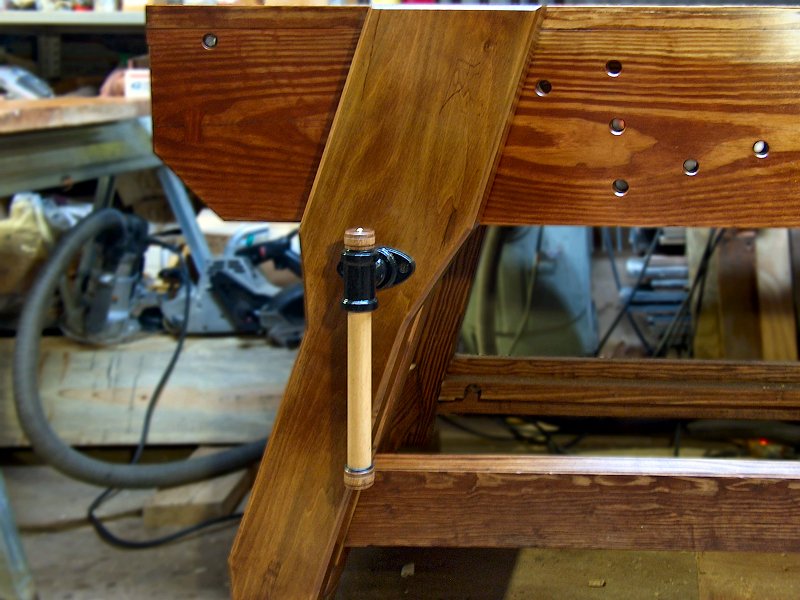
Installing the leg vise screw (6 photos).
Leg Vise Screw Installation
With the leg vise chop and parallel guide ready for assembly, I began
working on the leg vise screw installation. I wanted to get the screw in place and working properly before gluing in the parallel guide, since the
whole leg vise thing would bind up and be a mess if it wasn't aligned properly with the parallel guide.
The other consideration with regard to the leg vise screw was to make it so the entire leg vise has a little "toe-in" at the top in order for it to function correctly. Keep in mind, the leg vise is essentially a 3-foot long lever that can develop tremendous pressure. How one distributes that pressure is dependent upon the location of the parallel guide holes compared to the thickness of the stock being held. If the pin were set so the bottom is at say, 1-inch, and the stock to be clamped is at 3/4-inch, the vise chop would pivot slightly at the screw location causing only the very top edge to grip the work, and most of the pressure would be applied to the pin at the bottom (try this with a wooden pin and that thing will snap like a twig). The same problem arises if the stock is 1-inch think, and the pin is set for a 3/4-inch space at the bottom - the chop would now pivot in the opposite direction as it's tightened, gripping just the bottom edge of the stock up top, and placing most of the pressure against the pin at the bottom. The parallel guide pin locations should therefore be set as close to even as possible to the thickness of the stock. This will balance the pressure evenly between the stock at the top of the vise, and the pin at the bottom. However, with equal distances established between the pin and the stock, the leg vise chop will still deflect slighty in the center as it is tightened, and that will cause the top of the chop to pull away from the top edge of the stock, and more pressure to be applied to the bottom edge of the stock. This deflection is counteracted first by making the chop out of thick material - at least 2-inches thick to minimize distortion. Secondly, by pre-setting the whole vise so the top is a little closer to the leg than the bottom ("toe-in"), when the guide is pegged even with the stock, the top will hit the stock before the bottom hits the peg. Then as the vise is snugged tight and distorts slightly as the bottom tightens against the peg, the top pulls in parallel to the entire surface of whatever stock is up top for a secure grip. It's also worth noting that even if one avoids the whole parallel guide hole location mess and just goes for a crisscross parallel support, the chop still needs to have some toe-in for the crisscross to work properly, since the situation is the same with the crisscross as with evenly spaced stock and guide pin location.
Okay, so enough theory of leg vises - for all that stuff I just wrote to apply, the leg vise screw base needs to be installed so the threaded rod has a very slight angle up as it exits the bench leg. There's enough "slop" where the handle attaches to the rod that this won't effect screw function, but I wanted to get the hole for the screw marked and made before attaching the parallel guide. To set the angle of the threaded rod, I checked the existing angle with a small torpedo level (it was pretty much level), then removed the base and added a couple shims of card stock until the bubble in the level was just touching one line in the tube. This resulted in about an 1/8-inch of toe-in at the top of the chop, which is what I wanted. With the screw base aligned and installed, I next temporarily placed the guide into the mortise of the chop, and clamped that assembly on to the leg so I could mark the hole location for the screw in the chop. With the chop clamped in place, I carefully put a 1-inch auger bit through the screw base from behind, and marked the center for the hole on the chop. The vise screw is a 1-1/8 inch rod, so with the chop back on the bench I bored a 1-1/4 inch hole with the auger. The over-sized hole allows for the chop to move a little as it's tightened, and gives some room to adjust where the screw gets attached to the chop. For that, I put the chop and guide back on the bench leg, then clamped the screw in place and ran it through the full distance to adjust position and ensure nothing binds. Once it was set, I traced around the screw handle base, then aligned the screw mount holes so they'd be level and attached the screw to the chop. Almost done...
Parallel Guide Installation
The last step to installing the leg vise was to drill the parallel guide
pin holes and get the guide permanently attached to the leg vise chop. Looking back to the workholding plans above, I had laid out the hole locations
in two rows, with the holes in each row spaced 1-inch apart and one row offset from the other by a 1/2-inch. This would allow locating the first pin
to accommodate stock from 1/2-inch to 3/4-inch thick (with no pin needed for thinner stock, thanks to the toe-in addressed above), and then re-located
as needed in 1/2-inch increments to accommodate other stock sizes. Additionally, the two hole rows started 3/8-inch and 7/8-inch away from the chop.
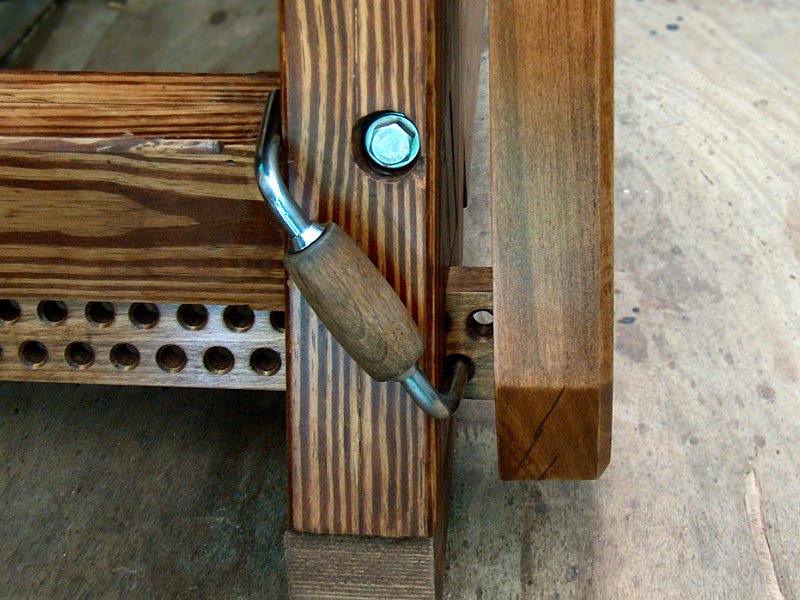
Parallel guide installation (5 photos).
I laid out the center locations for all the holes, then took a couple turns in each hole with a 1/2-inch auger bit to clearly mark their location. Next, I fitted the plunge router with a 1/2-inch upcut spiral bit (my "portable drill press"), and bored all the holes, followed by the chamfer bit in each hole along both sides to ease the edges. I then opened up the top and bottom of the chop mortise with a paring chisel to make some room for wedges, cut a couple long narrow wedges from a bit of scrap Oak, and the thing was ready for final installation. Easier said than done... the idea here is that the shoulder of the guide's tenon needs to be held snug against the mortise in the chop, while one drives the wedges in the end of the tenon to hold the thing together. Okay, so make a couple splits with a bench chisel in the end of the tenon, slather the thing with glue, then put the tenon in the mortise and drive the wedges into the splits to secure it. Nope... place the wedge... tap, tap, tenon shoulder is now a 1/4-inch away from the chop before the expanding end starts to grab. Hmm. The solution was to put some blocking on the floor beneath the end of the parallel guide, along with a small piece of scrap spanning the end of the guide. A pair of long bar clamps were then carefully hooked over the end block at the bottom, then drawn snug at the face of the chop. That clamp set up held the shoulder tight, and with the far end also on the blocks at the floor, the wedges could be driven home without the thing bouncing around and the clamps popping off (which only happened twice before I figured out why). After the glue for the wedged tenon cured overnight, I did a final clean up on the end of the tenon with the flush cut saw and block plane, then put a nice 1/2-inch chamfer around the perimeter of the chop.
The last thing the leg vise assembly needed was a proper parallel guide pin. This is where I went a little overboard (okay, if you've read anything else on this site, you know all I do is go overboard, but I digress). I didn't like the idea of sticking some big Phillips screwdriver or relatively expensive drawbore pin in the leg vise, but I knew the pin needed to be metal to withstand the pressure of the vise in action. I also didn't want to just stick a piece of bent metal rod in there, but wanted something with a nice wooden handle on it. With a little pokin' around in the tool shed, I spied the perfect solution. As you've likely figured out by now, I collect and use many vintage Stanley tools. Hanging off a shelf in the shed are a bunch of various Stanley bit braces and hand drills, along with a very rusty old Miller's Falls No. 1410 brace that belonged to my father. I'm not a Miller's Falls guy, but it was my dad's, and I couldn't bring myself to just toss it. Looking at it now, I noticed if a did a little tweak to the bends then removed the top handle and chuck, it would do the job perfectly as a parallel guide pin with a builtin handle. Yes, it'll destroy it as a hand brace, but dad's old tool will find a new home in the shop so why not? After a little time on the wire wheel for rust removal, beatin' on it with a hand sledge at the anvil, then putting a nice shine on it with the buffing wheels, I had my parallel guide pin. The leg vise was complete and ready for finish application at last.
Finishing the Leg Vise
With the leg vise assembly completed and working correctly, it only needed
finish application and some leather applied to the grip surfaces to call it done. Finish application required a few days for each coat of stain
and oil to cure between coats, and with Winter weather and Thanksgiving upon us, this worked out fine. Each morning the chop assembly
would get another coat of stain or oil out in the shop, then come inside to cure in the warmth of the house 'til the next day (if the weather
was mild I'd also spend the rest of the day in the shop working on the sliding deadman - see below). After two coats of stain and five
coats of oil, the unit was ready for some leather to line the jaws.
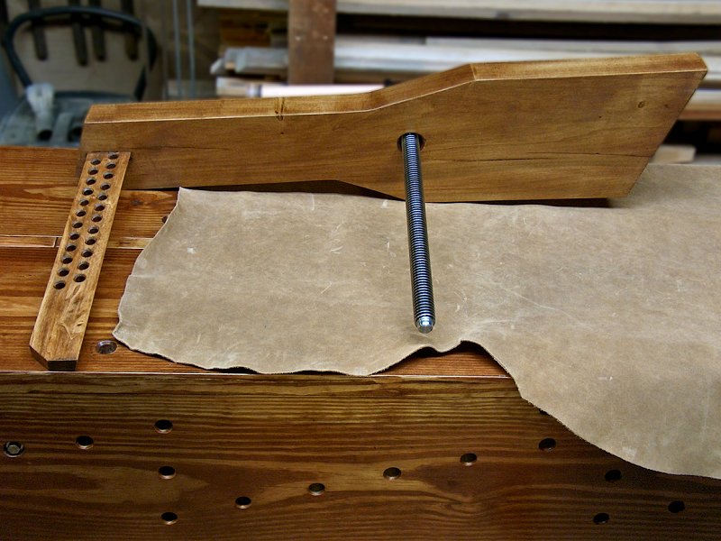
Finishing up the leg vise (5 photos).
I'd found a nice "medium gauge" piece of light brown suede cowhide on E-bay for around 40 bucks back in the Spring when I was
collecting materials for the bench build, and it was finally time to cut in to that. There are many options available for suede on E-Bay,
but I found ACS Trading Post
![]() seemed to have the best selection of suede
in the 4 to 6 ounce range (4 oz. gauge means it's about 1/16-inch thick, 6 oz. is 3/32-inch, etc.). I got a big piece so I'd have enough to
line the jaws of the leg vise, as well as the lengths I'll need for the Moxon vise when it comes time to put that together as well. I traced
the outline of the vise chop that contacts the bench apron onto the leather, then cut it to size. I worked the piece that attached to the apron
first, which also meant I needed to punch a couple holes in it to allow access to the apron bolt heads in case I ever decide to knock-down
the bench for moving or storage. I also glued this piece on with Titebond® Liquid Hide Glue, since I'd need
to be able to remove the area of the leather where it connects to the edge of the top in case of disassembly as well. I roughed up the
area of the apron where the leather would be applied with some 100-grit sandpaper to remove the finish and provide a little
tooth for the glue, then spread a thin coat of glue over the leather with a roller. Then I just slapped the thing on the apron and
held it in position with a large piece of scrap and a holdfast through the apron. The next day, I did pretty much the same thing to the
inside of the leg vise - roll on the glue, stick the leather to the roughed up surface, then screw in the leg vise with a piece of wax
paper between the jaws in case of any squeeze out and walk away. After the glue cured, the leg vise assembly was finished and ready
for use at last.
seemed to have the best selection of suede
in the 4 to 6 ounce range (4 oz. gauge means it's about 1/16-inch thick, 6 oz. is 3/32-inch, etc.). I got a big piece so I'd have enough to
line the jaws of the leg vise, as well as the lengths I'll need for the Moxon vise when it comes time to put that together as well. I traced
the outline of the vise chop that contacts the bench apron onto the leather, then cut it to size. I worked the piece that attached to the apron
first, which also meant I needed to punch a couple holes in it to allow access to the apron bolt heads in case I ever decide to knock-down
the bench for moving or storage. I also glued this piece on with Titebond® Liquid Hide Glue, since I'd need
to be able to remove the area of the leather where it connects to the edge of the top in case of disassembly as well. I roughed up the
area of the apron where the leather would be applied with some 100-grit sandpaper to remove the finish and provide a little
tooth for the glue, then spread a thin coat of glue over the leather with a roller. Then I just slapped the thing on the apron and
held it in position with a large piece of scrap and a holdfast through the apron. The next day, I did pretty much the same thing to the
inside of the leg vise - roll on the glue, stick the leather to the roughed up surface, then screw in the leg vise with a piece of wax
paper between the jaws in case of any squeeze out and walk away. After the glue cured, the leg vise assembly was finished and ready
for use at last.
Building the Sliding Deadman: Early Winter 2015
Other than the Moxon vise, which I've barely even
begun to consider, the last workholding addition to the finish the bench was the sliding deadman. This is supposed to just be a hunk o' wood that
slides along the bottom stretcher, with a long tenon in the top that fits into a dado on the bottom of the apron, right? How hard can that be?
Okay, so it's not a complicated concept, but getting it right turned out to be fairly involved - especially since I wanted to make use of those nifty
Stanley No. 203 bench brackets.
I suppose it wouldn't be all that hard to add a deadman to an existing bench, although plowing that dado in the bottom of the front apron wouldn't be a lot of fun on a fully assembled bench. On my bench, I found it useful to start planning for the thing as soon as I started turning raw stock into bench parts. Making the track the bottom of the deadman rides along on the front stretcher was the first early consideration. I made the track as a little 1-inch wide, 3/4-inch high triangle-shaped strip that was glued and screwed to the spreader back when I was assembling the bench base frame (see the "Final tweaks..." photos in the Readying the Base Parts for Finish section above for a close up of the track). As mentioned above, I offset the track from the face of the spreader by about 1/4-inch. This was done for two reasons: First, I prefer the angled track profile that sticks up, rather than a dado in the stretcher, so shavings and sawdust that will inevitably rain down from the bench top won't have any little corners to collect in and cause issues when trying to move the deadman. Second, offsetting the track from the face of the bottom stretcher allows the matching cut in the bottom of the deadman to have a little flat spot, rather than a somewhat fragile pointy end where it meets the stretcher.

The sliding deadman (11 photos).
The next early consideration regarding the sliding deadman was the creation of the dado track in the bottom of the apron. Because I laminated the apron from two pieces of 1-3/8 inch stock, I found it easiest to put a rabbet in each piece prior to glue-up, rather than plow the dado after they were laminated together. Also, because I'm eventually going to add a tool cabinet to the right side of the bench beneath the apron, the bottom track and top dado only extend as far as the tool box, and not the entire width of the apron. It was much simpler for me to clean out the stopped end of the rabbets with plenty of access, rather then chiseling out the end of a stopped dado.
The last thing I wanted to do to prepare for the deadman was to make it so the thing was fairly secure in the bench - the "standard practice" is to have say, a 1-1/2 inch tall tenon on the top, with 3/4-inch of that tenon fitting into a 1-1/2 inch deep dado in the apron. In order to remove the deadman, it's raised until the tenon shoulder meets the apron, then with the bottom clear of the track, the whole thing is swung clear of the bottom track and removed. This would mean the deadman tenon has to be a fairly loose fit (so it can be angled to clear the track), and when moving it along the length of the track, it could be unintentionally lifted off the track or angled and jam because of that extra space between the apron and the deadman's tenon shoulder. To resolve these potential problems, I made the dado and tenon the same size (with a few shaves taken off the deadman tenon to allow for seasonal dimensional changes), then I cut out a section as wide as the deadman at the end of the apron backer board rabbet so I could slide the deadman to that end, flip up a little wooden retainer toggle, and lean the deadman back through the cut-out to lift it clear of the bottom track and remove it when needed. See the "More front apron work" photos in the Front Apron Backer Board section above for close up photos of the apron dado and the deadman retainer toggle.
With my deadman track modifications taken care of during bench frame assembly, now I could simply cut a hefty piece of stock to fit, then bore a few 3/4-inch holes to hold a dog or holdfast and call it done... this is where things got a little more tricky, since I wanted to use my Stanley bench brackets with the sliding deadman. The Stanley No. 203 Bench Bracket is a wonderful little gizmo, produced from 1911 until 1942, with a hook that fits through a hole in a bench apron or leg, then hooks over the apron or leg to stay in place. When in place it provides a small shelf to rest stock upon, along with an adjustable-depth clamp to secure that stock between the bracket and the leg or apron. Getting these things to function in the apron or leg (or sliding deadman) while still allowing the use of a dog, peg, or holdfast is where the trouble comes in. The end of the 203 is not a nice, round, 3/4-inch diameter shaft like pretty much every other accessory available these days for a woodworking bench, but is instead a 3/4-inch by 7/8-inch oval shaped affair with a pointed end in line with the main shaft. The small part of that pointy-ended oval thing then forms a hook for the main shaft to hold the bracket against the leg or apron, and the opening for the hook requires the stock it's inserted in to be 7/8-inch thick. I guess lots of folks made their bench legs from 7/8-inch thick stock with 7/8-inch diameter dog holes back in the day, so Stanley made the hook to meet their needs (Stanley also offered the No. 207 metal bench dog from 1929 until 1974, and that had a 5/8-inch diameter shaft, so it doesn't make any sense to me either).
To make it so the deadman could accommodate the funky bench brackets, I made the deadman from two pieces of stock - the front piece was 7/8-inch thick, with 3/4 by 7/8 inch oval-shaped holes in it. That would allow me to insert the bracket, then give it a quarter turn to have it hook the back of the face board and stay in place. The face was laminated to a 1-1/2 inch thick back piece, and one side of the oval opening in the front lined up with a 3/4-inch hole in the back - which would allow me to insert a bench dog or holdfast to rest stock on if I didn't need the clamp of the bench bracket. I also had to add a 3/8-inch deep, 1-1/4 inch diameter countersink in the back board before gluing the thing together, so there would be some space between the boards to turn the hook and have it drop down and grab the front board. (You may have noticed in other photos that I also made these goofy, oval holes in the right leg as well - although with the legs I had to add the countersunk area to the back of the front leg piece, since it was 1-3/8 thick stock. Now you know why they're there). It all required some very careful layout to get right but it ended up working out beautifully.
Using two boards to laminate the deadman actually made fitting the thing a lot easier, since the top dado slot was set 7/8-inch back from the face of the apron, and the peak of the bottom track was 7/8-inch back from the face of the bottom stretcher (not a coincidence). The result was that to make the bottom, 45° angled dado v-grooved cutout (is there such a thing?), I only needed to make a 3/4-inch deep, 45° crosscut on the bottom end of each board. For the top tenon, the 7/8-inch thick stock was simply cut to fit between the apron and stretcher, and the 1-1/2 inch thick stock was cut long enough to include the tenon, then rabbetted off on one side to form the tenon when the two pieces were glued up. Please have a look at the photos in this section for more details of how this all came together.
After all that oddball, oval hole making and countersinking for clearance, the sliding deadman went together with glues and screws, then received the usual stain and Tung oil finish. With the sliding deadman completed, the workholding fixtures and vises were taken care of, and the bench build was nearly finished. Now all I need to make is the bottom shelf, tool storage stuff, a Moxon vise, some shooting boards, and a couple bench hooks...
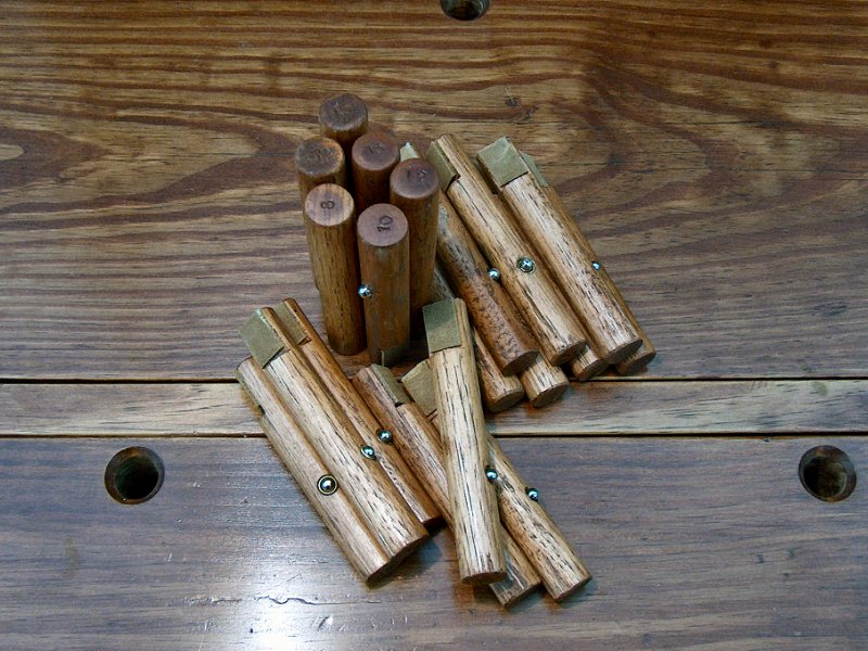
Making bench dogs (13 photos).
Dealing with those Dog Holes: Spring 2016
While working on the tool storage and shelving to
finish off the bench project (see below), I found more and more that I was having to clean stuff out of that first row of blind dog holes
along the front edge of the bench as I worked. Before I assembled the front apron, I had gone through and drilled a series of angled holes
in the back of the apron so I could insert a dowel for dog removal in case I buried a dog in one of those blind holes. This hole also helped
when cleaning out debris from those blind holes, in that it allows the vacuum cleaner to pull the stuff up without too much resistance. What has
become clear during bench use, is that I need a better solution to the debris problem than relying on occasionally vacuuming out the dog holes.
I decided the best course of action would be to fill all the dog holes with wooden dogs, then make use of those removal holes by fitting some
manner of contraption that allows me to lift the dogs and access the one or two hole positions needed for the particular task at hand.
Making the wooden bench dogs turned out to be a little frustrating, as it seems drill makers and dowel makers have different ideas of what
3/4 of an inch means. The Russell-Jennings 3/4-inch auger bit and the MLCS 3/4-inch upcut spiral bit are, according to the calipers,
indeed 3/4 of an inch in diameter, as is the resulting hole they create in the stock. The Poplar dowel stock from the hardware store
and home center is about a fat 1/32-inch oversize. It doesn't sound like much, but the 3/4-inch dowel simply will not fit a 3/4-inch hole.
I would guess the easiest solution would be to chuck the 36-inch dowel stock into a lathe, and spin it up while holding a sanding block
against the stock. I don't have a lathe, and didn't want to bother my woodworking friends with the time and travel needed to sand a handful
of dowels. I instead considered buying pre-made wooden dogs from Time Warp Tools
![]() , and while those have received rave reviews from many
woodworking and bench bloggers, I felt the cost of getting twenty of them was prohibitively expensive (over $150). I was going to have to make my own
set of dogs.
, and while those have received rave reviews from many
woodworking and bench bloggers, I felt the cost of getting twenty of them was prohibitively expensive (over $150). I was going to have to make my own
set of dogs.
I started by ordering a few 3-foot long, 3/4-inch Ash dowels from Cincinnati Dowel &
Wood Products ![]() , hoping these would be closer
to a true 3/4-inch diameter. Unfortunately these were also just a tad too big for the 3/4-inch dog holes, so I ended up using a hollow plane to take
a few shaves off each dowel until it fit easily. I then marked the length of each dog for each blind dog hole, and found there was enough
variation in the lengths to warrant numbering all the dogs so each one fit a specific location. The rest of the process was fairly straight-forward,
using a quick couple jigs for the band saw to cut a 2° flat on each dog, then do some drilling to add a 1/4-inch bullet catch to each dog to prevent
the things rattlin' around in their holes or rolling off the bench. Naturally, I applied stain and a few coats of oil finish to everything, and finished them
off with a little pad of leather on the flat face just because I could. Please see the photos above left for more details regarding making all the dogs.
, hoping these would be closer
to a true 3/4-inch diameter. Unfortunately these were also just a tad too big for the 3/4-inch dog holes, so I ended up using a hollow plane to take
a few shaves off each dowel until it fit easily. I then marked the length of each dog for each blind dog hole, and found there was enough
variation in the lengths to warrant numbering all the dogs so each one fit a specific location. The rest of the process was fairly straight-forward,
using a quick couple jigs for the band saw to cut a 2° flat on each dog, then do some drilling to add a 1/4-inch bullet catch to each dog to prevent
the things rattlin' around in their holes or rolling off the bench. Naturally, I applied stain and a few coats of oil finish to everything, and finished them
off with a little pad of leather on the flat face just because I could. Please see the photos above left for more details regarding making all the dogs.
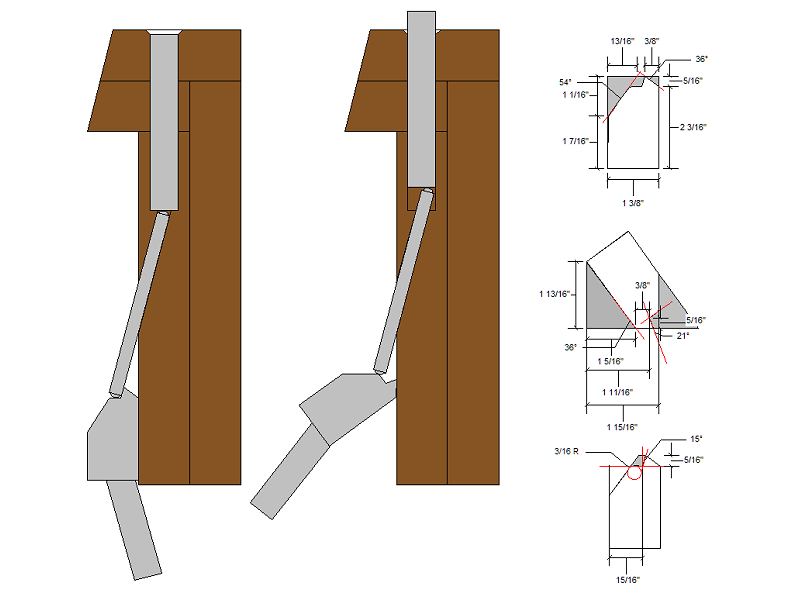
My goofy idea to lift the dogs from the blind holes (1 image).
The Bench Dog Lifter Contraption: Winter 2016/17
Having the row of front blind dog holes filled
with wooden dogs certainly prevented those holes from filling with scrap while using the bench. Instead, those holes were now filled with bench
dogs. I needed to come up with a way to lift the wooden dogs for use, or remove them to allow insertion of a Wonder Dog®
surface clamp, brass dog, or other workholding fixtures. As mentioned above, I had drilled a series of angled holes in the back of the front
apron which let me stick a dowel into the apron and pop up the wooden dog. The trouble was dowels didn't stay in the holes, and when I
eventually get the tool storage box installed, I won't be able to reach the lifter dowels above the tool box on the right side of the
bench. While doing yard work and tinkering with other projects throughout the Summer of 2016, I eventually worked out an assembly that
looked like it would do the job. The result is the plan sheet on the right.
Getting from something on paper that looked like it would do the job to actually building and installing the stuff took quite a while. Dealing with Fall yard clean-up, the holidays, and Winter snow storms, kept delaying the project, although I also had time to ponder how I was going to build this thing. The key to this thing working as intended would be to getting the angles right on the profile, and ensuring the fulcrum / hinge pin location was correct so the thing would pivot up without snapping the dowels off. One thing that became clear was that I'd have to remove the front apron from the bench in order to install the lifter hinges, which was something I wasn't looking forward to doing. I finally dedicated some time to it in early 2017 and just jumped in.
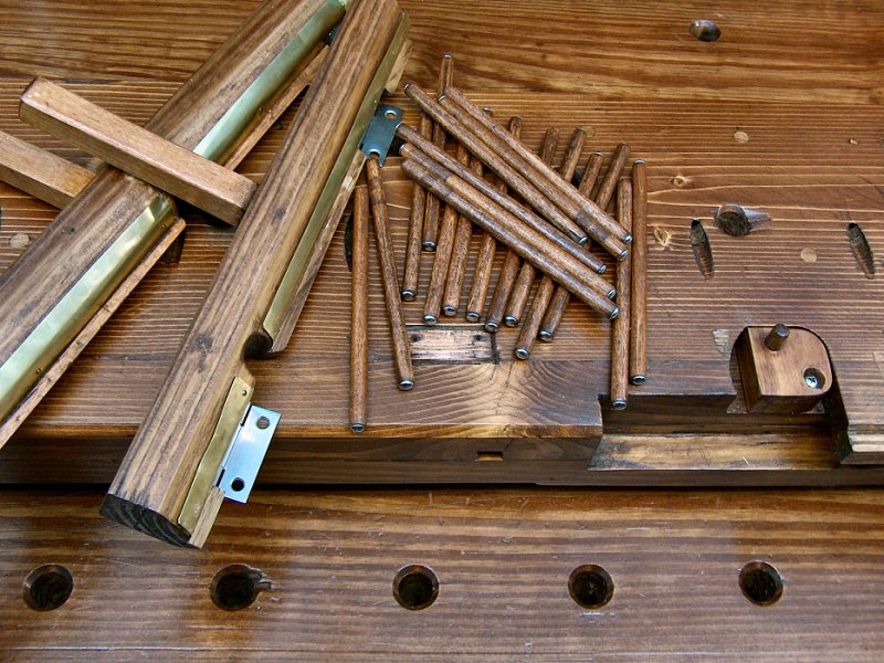
Building the dog lifters (10 photos).
Construction started with stock selection, and I managed to find enough scrap pressure-treated two-by material hangin' around so I didn't need to purchase new stuff and wait weeks for it to dry out. I planned to build the lifters as three units, with one about 30-inches long to lift the nine dogs that span the tool box and deadman removal slot on the right half of the bench, another about 24-inches long to lift the six dogs near the center, and one about 16-inches long for the four dogs remaining at the left end of the bench. I cut the stock to length, then roughed out the dimensions on the bandsaw with final dimensioning through the thickness planer. I left the pieces extra tall, since I needed some material in place to do the angle cuts. The first of those was roughed out on the bandsaw, with the table tilted to create the 36° face. The stock was then clamped on the bench at an angle so I could hand plane down to the line and get that angle just right. To cut the little shelf where the lifter dowels would sit, I had to dig the table saw out of storage since that was the only way I could figure to make the cuts needed for the dowel shelf. I added a fence set at 36°, then set the blade to 21° and passed each piece over the saw to create the 15° section for the back of the dowel shelf (this is the cut shown in the right-center drawing of the plans). I then re-set the blade to 90°, raised it up and shifted the fence for another pass that created the 54° face. The angled fence was then removed, the blade lowered and the stock flipped to make the final cut for the bottom bit of the dowel shelf. I was glad to be done with goofy angles and power tools, to be sure.
Next I cleaned up all the cut facets with a shoulder plane on the bench, then clamped the lifter stock to the bench to mark where each dowel would land on it and work out the hinge locations as well as determine where the front apron holes might interfere with the lifters. I selected some Stanley stainless-steel 2-inch wide hinges, and put two hinges on each section. With the hinge locations and apron through-holes determined, I then cut away the back part of the lifter shelf for clearance, and carefully marked and mortised the dowel shelf for the hinge leaf. This was a critical bit of assembly, since the hinge knuckle needed to be centered on the apex of the angles of the lifter faces that touch the apron in the rest and lifted positions. Before applying finish to the lifter mechanisms, I decided to add a Brass "wear strip" to the hinge shelf to endure the lifter dowels didn't just make a groove in the shelf rather than actually push up the dog. I also needed to add a handle to each lifter, which I made from some scrap Maple (see the photos above for more details).
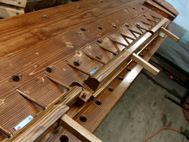
Installing the dog lifters (9 photos).
With the assembly of the lifter mechanisms completed, I then stained them to match the rest of the bench. I also applied the usual five coats of oil mixture to everything over the course of a few days. In between applying the oil, I set about removing the front apron from the bench. The only area of concern was the leather lining that spanned the apron and the edge of the bench top at the leg vise. A few minutes with a heat gun loosened up the hide glue enough that I could peel off the leather that was glued to the top edge, and the rest of apron unbolted without incident. I kept the apron loosely secured in place so I could use the leg vise to hold the lifters while I attached the hinges and Brass strips after the finish was applied, then removed the apron and flipped it over on to the bench. I then seated all the dogs in their holes in the apron, inserted the lifter dowels, and clamped the lifters into position to mark the locations for the hinge screws. I then temporarily mounted the lifters with the 5/8-inch screws they came with to secure them, and traced the hinge mortise locations with a marking knife. Next I removed everything, marked the mortise area for the hinge knuckle with a spare hinge in place, and chiseled the hinge mortises in the back of the apron. After a little clean-up with the router plane, the lifters were ready for attachment to the apron.
Final assembly went very smoothly. First, I re-drilled the hinge screw holes in the apron to accommodate the longer 1-1/4 inch screws that
I used to replace the short screws that came with the hinges. Next, I checked all the dowel holes with a 3/8-inch auger bit, running the bit
into each hole to ensure there were no splinters or other obstructions that might cause the dowels to bind. Before sliding each dowel into position,
I gave the dowel and hole a little dab of
Slipit™
![]() wood lubricant to keep things moving smoothly.
I then screwed the lifters in to position, and re-attached the front apron to the bench. With a little apprehension I gently pushed the handle
back to see if these silly lifter contraptions would actually work, and I was a bit surprised to see all the dogs pop up from the bench without
any trouble! The thing actually works - no binding, no broken dowels with dogs stuck in the bench. I'm very proud and pleased with how well it
worked out, and certainly glad to have this part of the build behind me.
wood lubricant to keep things moving smoothly.
I then screwed the lifters in to position, and re-attached the front apron to the bench. With a little apprehension I gently pushed the handle
back to see if these silly lifter contraptions would actually work, and I was a bit surprised to see all the dogs pop up from the bench without
any trouble! The thing actually works - no binding, no broken dowels with dogs stuck in the bench. I'm very proud and pleased with how well it
worked out, and certainly glad to have this part of the build behind me.
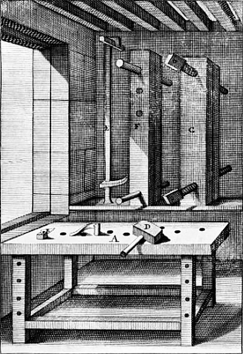
The double-screw vise history & plans (3 drawings).
The Double-Screw Vise: Spring 2017
Time for a reminder of why one builds a joiner's bench, which
is to allow one to securely hold stock while working the faces, the edges, and the ends of the stock. With most of the bench assembly completed, the
first two goals have been accomplished: The front apron and leg vise provide me with an easy method of holding material for edge work at the ideal
height, just as the tail vise, bench top dog holes & holdfasts, and planing stop provide a means to hold material for face work on a single
board or wide panel. Due to the height of the bench (34-inches, in my case), working the face and edge of stock may be accomplished with good
leverage on the tooling, and no stress on my back or arms. Working on the ends of stock for joinery work however (cutting tenons, dovetails, etc.),
is still not ideal at this bench height. Stock may be held upright for end work with the leg vise and front apron, but to raise it up sufficiently
to view details, as well as to relieve back strain while working with a saw or chisel for an extended period of time, the stock should really be in the
42-inch to 48-inch height range for me. In order to do that, the stock ends up sticking up from the bench at least a foot, and is libel to flap
around a good deal while working on it with that much unsupported material above the holding mechanism on the bench.
A good solution for holding stock vertically was first addressed in English in Joseph Moxon's Mechanick Exercises in 1678. Moxon illustrated a double-screw vise attached to the front of his bench, although his text described securing it to the bench top for actual use. Schwarz then discussed the usefulness of the double-screw bench top vise for stock end joinery work on his blog in 2010, as well as his first workbench book published that same year. Since then it has become well known as the "Moxon" vise. However, that's not correct - the bench top double-screw vise was apparently first published in André Félebien's Principes de l'architecture, de la sculpture, de la peinture, &c. in Paris in 1670, with the device described and illustrated in his plate XXX (shown at left). Rather than call it a "Félebien vise", which no one would recognize, I'm simply going to refer to it as a "double-screw" vise, and get on with building the thing. As with any of my projects, I started with a set of detailed plans. I also altered the simple double-screw vise by adding a shelf to the rear jaw to accommodate lying stock flat at a raised height while doing joinery work. With the addition of the rear shelf to the double-screw vise, I'm really building a "bench-on-bench double-screw vise" unit.
Regardless of what it's called, construction began with stock preparation, using a couple 2x8x8 and a 2x6x8 that were picked up nearly a year ago to dry out and build this thing. I also had a very old, small Maple workbench that had been given to me by a friend years ago when he remodeled his basement from a shop into a TV room. The bench was about 2-1/2 feet deep by 3-1/2 feet long with fold-up legs and very wobbly (My guess is it was a "C. Christiansen Co." bench from the 1950's). I had removed the broken, fold-up legs and placed the top and vise assembly on a small frame of 4 x 4's to make it usable, but just barely. It did have a pair of nice wooden vises built into it with 1-1/2 inch by 1-foot long threaded wooden vise screws. The bench and vises were taken apart, which provided the pair of vise screws and "nuts" cut from the old frame this new unit needed.
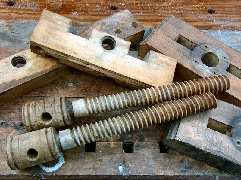
Construction of the double-screw vise (22 photos).
Referring to the plan sheet, I cut the stock to rough length then planed and jointed it to final dimensions. I then glued together the stock for the jaws and bench top, and used the router to cut the few rabbets and dados that provide the joinery for the frame unit while the glue cured. Everything then got a little final joinery fitting with hand tools before putting it all together. That's were assembly of this thing became a little tricky - if it was just a double-screw vise, then I could have simply fitted the vise screws to the jaws and called it done. The problem with adding that bench-on-bench business is all the perpendicular wood connections involved with the frame-to-top and frame-to-inner jaw connections. Slathering everything with glue and screwing it all together would have resulted in a frame that would almost certainly split or have a joint fail somewhere when the wood moved with seasonal humidity changes. To try and compensate for the inevitable wood movement, I only used glue where the front edge of the top sits on the inner jaw, as well the front edges of the base and frame connections. The rest of the base and frame connections were dry fit, and held in place with "Roman" cut nails from the Rivierre Nail Factory (I think Félebien would approve). The glued together bits should keep the front jaw properly aligned, and encourage any wood movement to take place toward the back of the frame where the nails and dry joints will allow expansion without splitting anything. Time will tell. I also added a handful of 3/4-inch holes in the top to accommodate dogs or a holdfast to aid with workholding. Please see the photos at right for details of assembly and finishing.
The bench-on-bench double-screw vise came out better than I thought it would, and I find I tend to leave it attached to the bench almost all the time. Having that extra few inches of work height has really allowed doing detailed joinery work much easier on my back, and the 10-foot bench still leaves plenty of room to work without having to remove the unit. Now I can put it to work making the drawers for the tool storage cabinet, and the joiner's bench will be finished!
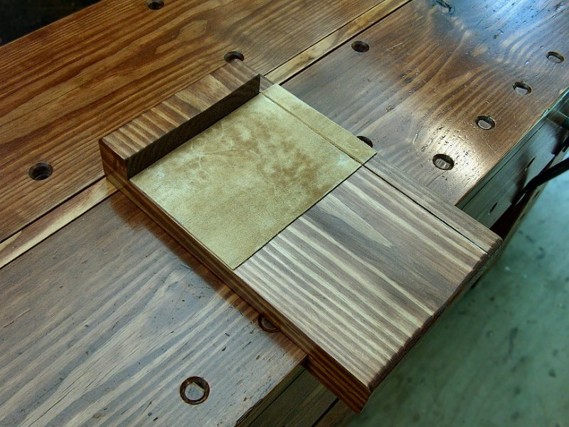
Bench workholding appliances (14 photos).
Additional Workholding Appliances: Summer 2017
As I started working on the tool storage box for the
bench, I also had a chance to work on a few of the extra workholding appliances that make life easier with a traditional joiner's bench. These are
simple assemblies that sit on the bench and allow work to be held for cross cutting with a hand saw (the bench hook), cleaning up end cuts with a plane
(the shooting board), or securing stock for moulding plane work (the sticking board). In late May and early June I had done some work on a pair of
picnic table assemblies for our church campus, using frame kits they purchased and wood that we supplied. In April we had purchased a bunch of 10-foot
2 x 10 stock for the tables, which were going to be 8-feet long, and stickered it all in a friends shop to dry out while we waited for the frame
kits to show up. After the tables were finished, I ended up with all the 2-foot cut-offs, so that's what I used for the bench appliances.
Bench hook assembly began by planing all the stock down a bit more to clean up both faces and get everything to 1-1/4 inch thick. I then cross-cut each piece to provide the stock for the fence or hook, and simply glued and screwed the bits together. After the glue cured, I then finished each piece with stain and a few coats of oil/varnish blend. While these appliances are generally considered disposable, I still figured I'd make them look nice and match the rest of the bench. I also had some extra leather after using most of it to line the vise jaws, so I applied that to the surfaces of each piece with hide glue to help hold stock without slipping. The shoot board got a little fancy, as I wanted to add an angled bed for the plane to ride on. That required a bit of a goofy set up with the table saw to do an angle rip in the edge, but it worked out fine. My only concern with the shooting board is that I probably should have made it with the angle run "downhill" rather than up, since the way it is now results in a tiny bit of tearout at the far upper corner (but only if I neglect to add a little piece of scrap between the stock and the fence). We'll see how it goes for now.
The last appliance I worked on was a sticking board, which is used for holding stock when creating mouldings by hand (and yes, this is something I'd really like to work on, especially after reading Bickford's Mouldings in Practice). A friend of mine had a few sheets of 10-ply Baltic Birch he'd purchased for a project, and I managed to get him to rip off a few strips for me to use for the shooting board stock. The base of the shoot board is 5-inches wide, with a stack of 1-inch wide strips on the edge to create the fence (for a 4-inch wide work surface). I added some small tabs of plywood to the base piece so I could secure the unit to the bench with holdfasts, then stacked a couple strips on the edge with glue and screws to form the fence. I also added Brass threaded inserts to the end to secure the 1/4-inch Brass screws for the end stops, as well as along the top of the fence to allow me to add extra 1-inch wide strips if I need a taller fence. The Baltic Birch is very stable, and with the Brass inserts for the machine screws (instead of using wood screws, which just chew up the end of the board eventually) this thing should last a while. Now I just need to get that tool storage box built.
Tool Storage & Shelving
With most of the workholding additions completed over the Winter of 2015, I turned my attention to adding some manner of tool racks to the bench top and getting the bottom shelf installed. I was also finding it a bit of a chore to chase extension cords around under the bench, so I decided to deal with power distribution for the bench as well.
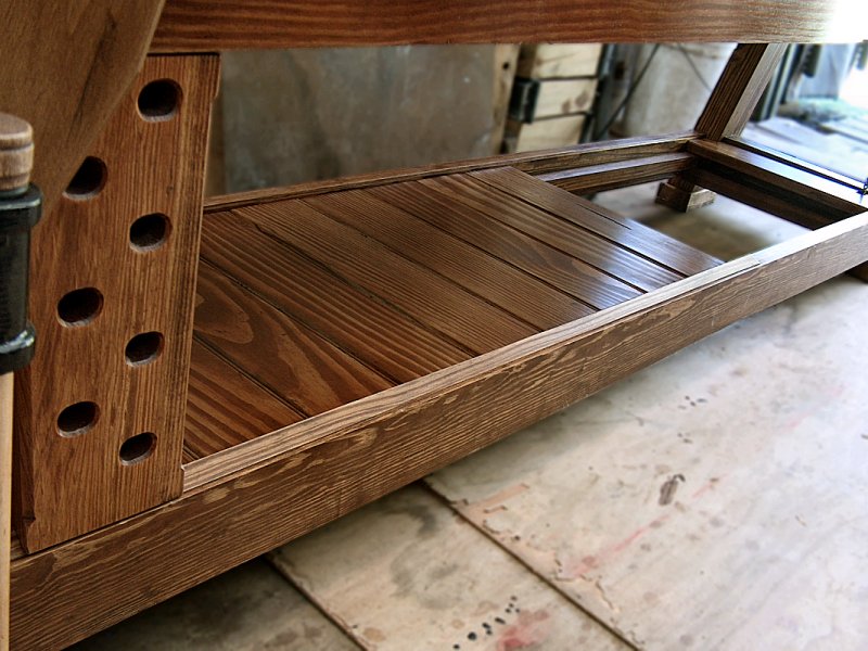
The bottom shelf (9 photos).
Bottom Shelf Installation: Early Spring 2016
I had purchased the stock for the bottom shelf and
tool box not long after the bench frame was finished, and it was finally dry enough to stop moving it around the shop and do something with it.
Besides, now that I had a functional bench, I could easily address the workholding tasks required to ready the shelf boards for assembly. The shelf
support rails for the bottom shelf had been installed such that I could use stout, 5/4 decking to make the shelf boards with the surface
of the shelf just shy of the tops of the stretchers to ensure nothing would roll off the shelf onto the floor. I started by cutting the 10-foot
lengths of 5/4 stock in to 33-inch sections for easier handling during surface preparation. Once I decided what face would end up as the "show
surface", I then planed that face a bit to remove milling marks, and gave it a quick once-over with some 150-grit and the belt sander.
Next, I ran each piece through the band saw to remove one of the rounded edges of the 5/4 deck board, jointed the cut edge, then ran it
through the band saw again taking a very light cut from the other side to ensure each board had parallel sides (the round-over of the second
side would be removed when cutting the tongue for the tongue & groove edge joints).
With the stock surfaced and jointed, I then cut it all to 16-1/2 inch lengths (the final length is just under 16-inches) and took a few minutes to lay out the boards to create a pleasing grain pattern from one board to the next. Once I'd settled on the arrangement, I flipped them all and marked the order with Roman numerals lightly chiseled into the back on one end. By marking the boards, I could keep track of the order I had determined, as well as which sides get the tongue and which gets the groove. Next, I ran the stock through the router table to create the tongue & groove edge joints, then added a 3/16-inch bead to each board face next to the tongue. I then cut all the stock to final length, and took a few days to get the usual stain and oil finish applied to everything. Installation was completed with a pair 18 ga. brads through the tongue of each board - they hold well enough to prevent the shelving from rattling and bouncing during bench use, yet a simple tap from below and the shelving can be removed if needed.
Bench Top Tool Racks: Spring 2016
Over the course of a few months of working with the bench to
complete the vises, workholding fixtures and bottom shelf stock, it became clear that some manner of tool or bench dog holding device would be
a very useful addition to the bench. Roubo's plate 11 illustration (here it is again if you need a reminder)
shows a tool rack at the back left of his bench design, and after using my bench a while, I finally figured
out he was on to something a couple hundred years ago. I decided to add a pair of tool racks that would bolt in to the bench along the back
of the bench top. Because there is no rear apron, I surmised I could bolt the racks up to the bottom of the bench top, with the edge of the
rack held against the angled top stile. I didn't develop any detailed plans for the things, but just kind of figured them out as I went along,
with dimensions based on the bits of scrap wood I had left over from the bench build. The racks ended up with each one about 16-inches from
the end of the bench, and each rack is about 16-inches long with a useable section that's 3-inches wide. Each rack was laminated together
using a chunk of 2 by 8 that fit beneath the bench and against the top stile, then a piece of 2 by 3 was added to the top of that so the top
edge rested against the back edge of the bench top. The top piece was still about 1-3/8 inches below the bench top (remember, the bench is
2-3/4 inches thick), so if I need to work on something large the extends over the back of the bench, I can empty the rack and it won't
interfere with the work.
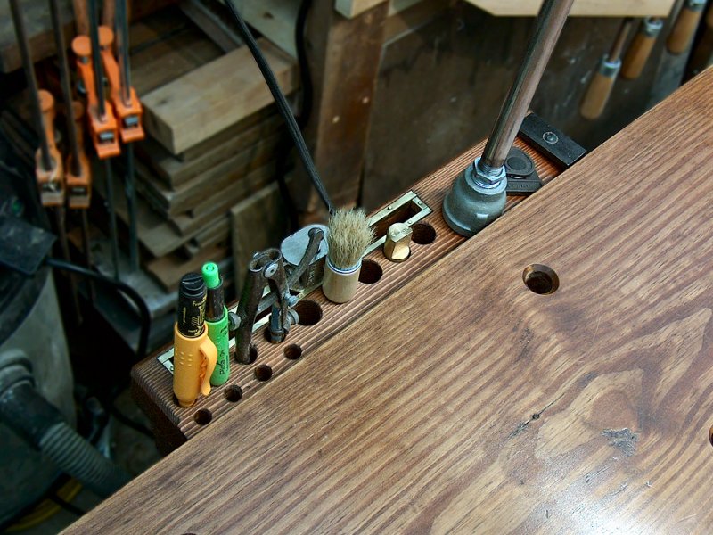
Making & attaching the tool racks (15 photos).
Getting the two racks attached to the bench turned out to be a little problematic, since I had taken great care when designing and
building the bench to eliminate any bolts heads in the top. The simplest solution of course, would have been to just get over it
and countersink in a couple 3/8-inch bolts to secure the racks. Not an option at this point... Next easiest would have been to drive
a couple beefy lag bolts through the racks and into the bench top from below, but I wanted the ability to remove the racks when needed,
and lags in wood have a tendency to strip out their holes after a few removal and re-insertions. After mulling my options over for a
few days, I found the Veritas®
3/4" Bench Anchors ![]() and, while a bit
pricey, these looked like they would do the job nicely. I ordered four of the anchors, and also grabbed a pack of threaded inserts from
McMaster-Carr
and, while a bit
pricey, these looked like they would do the job nicely. I ordered four of the anchors, and also grabbed a pack of threaded inserts from
McMaster-Carr ![]() to reduce the anchor thread from 1/2"-13 to 3/8"-16 to allow more fastener options. My first idea was to hold the rack in place then
attach it with a pair of 3/8-inch bolts threaded into the bench anchors. I found that attempting to get the bolts to catch while holding
the rack with one hand, and spinning the bolt with the other hand while working blind and upside-down was nearly impossible. I needed to
work out a different mounting method to attach things to those anchors. I pressed on with making the racks however (as well as working on
the bottom shelf and all those bench dogs), and figured I'd come up with something eventually.
to reduce the anchor thread from 1/2"-13 to 3/8"-16 to allow more fastener options. My first idea was to hold the rack in place then
attach it with a pair of 3/8-inch bolts threaded into the bench anchors. I found that attempting to get the bolts to catch while holding
the rack with one hand, and spinning the bolt with the other hand while working blind and upside-down was nearly impossible. I needed to
work out a different mounting method to attach things to those anchors. I pressed on with making the racks however (as well as working on
the bottom shelf and all those bench dogs), and figured I'd come up with something eventually.
For the 3-inch by 16-inch exposed portion of the tool racks, I decided to create an area that was a 1/2-inch wide slot to hold chisels or saws, then bore a few 3/4-inch, 3/8-inch, and 1/2-inch holes to hold bench dogs, other workholding fixtures, screwdrivers, marking gauges, etc. I was also considering putting some manner of electrical outlets on the racks, and also use them to hold some bench lighting fixtures. The first step was to make the slotted section, and I decided to build the rack so the slot would overhang the lower support piece so it only had to be cut through one piece of stock. I also had the idea to line the top edge of the slot with Brass to prevent the edges of the slot from getting chewed up with inserting or removing saws and chisels. I cut the slots with the bandsaw and glued the stock back together, rather than bother with making a long mortise. Next, I purchased some light gauge Brass strips from the local hardware store, and formed those into tiny pieces of angle to use to run around the edge of the slots. I then laid out and bored the holes based on what I was planning to store in each rack. Next the top section was glued to the bottom support piece, and after a little light sanding and chamfering the edges to match the rest of the bench, the racks were ready for stain and oil finish. I just had to figure out a better mounting method.
After some thought and while browsing the bins of fasteners at the local hardware store, I decided to replace the through bolt fastening method with 3/4"-16 Stainless Steel studs that were permanently attached to the bench anchors. I could then position the edge of the rack against the top stile of the bench, swing it up over the studs, and secure it in place with a couple wing nuts and washers. This turned out to be much easier to accomplish without having to crawl around under the bench to see what was going on. One of the reasons I wanted to make the racks removable was to ensure I could get them out of the way if I needed to slide a carcass over the bench, and the studs hanging off the back bottom of the bench top wouldn't be an issue if that need arises. I also added a piece of stock to the tool rack behind the bench that has some carriage bolts through it, which provides a place to re-attach the rack (and still reach it easily) in the event it needs to be removed from the bench. As usual, please look over the photo gallery above for more details of the assembly and mounting tasks.
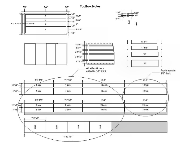
The tool storage box drawer plans (1 image).
Bench Tool Storage Box: Spring 2018
The last thing to address on the bench build was the tool
storage box that I had planned for the lower right area of the bench. I had originally purchased some "under drawer" drawer slides,
but it was clear now that the bench was mostly done that there simply wasn't going to be room for any drawer hardware in the tool box. To get
started I made a quick plan, as usual, and tried to get all the sizes for the drawers worked out. I will mostly be storing measuring and
marking tools in this box, so a few thin drawers should work fine. For drawer slides, I'll just use 3/4-inch square rails, let in to
the sides of the box with a stopped dado in the drawer sides.
With the plans mostly worked out, I started work on the box by gluing up some 3/4-inch pressure treated 1 x 8's I'd purchased a while ago for this box so it could dry. After the glue cured I then smoothed out the large piece with the hand planes, then cut it into the pieces I'd need for the case assembly. I also cut up more 1 x 8's to for all the drawer stock pieces, according to the plans. For the drawer runners, I had some nice Ash that a cut up into 3/4-inch by 3/4-inch pieces, with a little extra length to trim to size during box construction. Next, the stopped dadoes were cut into the two box sides with the router, and the carcass was ready for assembly.
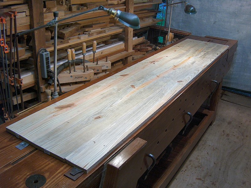
Building the tool box carcass (5 photos).
The carcass assembly was very basic, with simple half-lap joints to provide a little extra glue surface for the
connection of the sides to the top and bottom, then held together with 1-1/2-inch clout square-cut nails from
Lee Valley
![]() (and lots of clamps, of course).
After a little scraping and light sanding to clean up the carcass (the back will get nailed on after the drawers are all fitted),
it was time to move on to the drawer work.
(and lots of clamps, of course).
After a little scraping and light sanding to clean up the carcass (the back will get nailed on after the drawers are all fitted),
it was time to move on to the drawer work.
More photos and updates to follow as work progresses.

Task lighting & power distribution (5 photos).
Power Distribution & Task Lighting
Another unplanned addition to the bench that came to mind while
considering the tool racks, was to add some power outlets for the bench incorporated into the racks. The reality of a joiner's bench in a
modern shop is that there will be occasions where "tailed" power tools are desired to perform various tasks. I find I'm often reaching for
belt sanders, the router, or the biscuit joiner, then dealing with some tangled extension cord under the bench to get the thing powered. I also
found times when the overhead 10-foot florescent light wasn't adequate for the task at hand. I wanted to have a couple bench mounted lights I
could use for close-up work, or position as raking light for surface prep and finish application projects.
I addressed the lighting needs first (and if you notice the dates on the photos, I actually got these built before I started on the tool racks, above).
The simplest solution would've been to grab a couple desk lamps and a pair of
Lee Valley Lamp Bushings
![]() and move on, but I just didn't feel those would look
proper with the rest of the way the bench had turned out. I remembered I had a box with some old work lamps and other fixtures in it sitting in
storage from back when I had my car shop in the 100+ year old United Shoe Machinery building. I wasn't sure what I had, but figured it might be worth
checking out. I was pleasantly surprised to find I had four O.C. White Co. articulated task lamps - two complete with swivel bases, and two with just
the upper arms and adjustment supporter mechanisms. I recalled running across the O.C. White Co. name in the past while re-wiring some industrial
lighting for one of my brother's restaurant projects, and after a little digging around I found a few examples of these lamps at
Urban Remains™
and move on, but I just didn't feel those would look
proper with the rest of the way the bench had turned out. I remembered I had a box with some old work lamps and other fixtures in it sitting in
storage from back when I had my car shop in the 100+ year old United Shoe Machinery building. I wasn't sure what I had, but figured it might be worth
checking out. I was pleasantly surprised to find I had four O.C. White Co. articulated task lamps - two complete with swivel bases, and two with just
the upper arms and adjustment supporter mechanisms. I recalled running across the O.C. White Co. name in the past while re-wiring some industrial
lighting for one of my brother's restaurant projects, and after a little digging around I found a few examples of these lamps at
Urban Remains™
![]() in Chicago. After seeing the prices associated
with these things, not to mention just how cool they are, I knew a couple of these were going to have to find a home on my bench. I left the pair
with the cast swivel bases in storage (they'll certainly find a home when the garage gets built), and got to work cleaning, polishing and re-wiring
the two that had no base. I had to add a couple new sections of 3/8-inch pipe for the main shaft, then worked out a base assembly with some additional
fittings and a 3/4-inch dowel sticking out of the bottom. With this base arrangement, I could re-locate the lamp to any existing dog hole in the
bench top as needed for close-up work, and easily keep it stored in the tool rack for general area lighting.
in Chicago. After seeing the prices associated
with these things, not to mention just how cool they are, I knew a couple of these were going to have to find a home on my bench. I left the pair
with the cast swivel bases in storage (they'll certainly find a home when the garage gets built), and got to work cleaning, polishing and re-wiring
the two that had no base. I had to add a couple new sections of 3/8-inch pipe for the main shaft, then worked out a base assembly with some additional
fittings and a 3/4-inch dowel sticking out of the bottom. With this base arrangement, I could re-locate the lamp to any existing dog hole in the
bench top as needed for close-up work, and easily keep it stored in the tool rack for general area lighting.
With the lighting taken care of, I wanted to work out some power distribution to the bench. My original idea was to use a couple covered
floor outlet boxes built in to each tool rack. My desire was to have outlets that faced up for easy access, but I was concerned about filling
the outlets with sawdust and shavings when not in use. After seeing the cost of covered floor outlet boxes, I had to re-think how I was going
to add power and started looking at power strips. The problem with power strips was again, how to get at the plugs without crawling around
under the bench, and how to keep sawdust out of them if I mounted them with the plugs facing up. While browsing power strips at Amazon, the
solution presented itself: I could mount the power strip on the bottom of the tool rack facing down, then add a couple
1-foot extension cords
![]() to the power strip that may be easily
grabbed by reaching over the top of the bench to connect tailed tools. With that finally worked out, I purchased the short cords, and a couple
five outlet, unswitched, heavy duty power strips to mount under the tool racks. I opened up the right rack power strip and shortened the cord
to just long enough to plug in to the left rack power strip. For the left rack power strip I purchased one with a 15-foot cord so I could
easily power the bench when it later finds a home in the garage, and coiled that up for now and hung the coil from the tool rack. After a few
weeks of use, I've found the power strips have worked out great - they don't fill with sawdust when not in use, yet I can get at them easily when
needed (and they're not visible at all, which is a bonus in my mind).
to the power strip that may be easily
grabbed by reaching over the top of the bench to connect tailed tools. With that finally worked out, I purchased the short cords, and a couple
five outlet, unswitched, heavy duty power strips to mount under the tool racks. I opened up the right rack power strip and shortened the cord
to just long enough to plug in to the left rack power strip. For the left rack power strip I purchased one with a 15-foot cord so I could
easily power the bench when it later finds a home in the garage, and coiled that up for now and hung the coil from the tool rack. After a few
weeks of use, I've found the power strips have worked out great - they don't fill with sawdust when not in use, yet I can get at them easily when
needed (and they're not visible at all, which is a bonus in my mind).
Bench Materials & Costs
For almost all of the renovation projects we've undertaken over the years working on the house and garden, I've rarely taken the time to give serious consideration to determining the exact cost of those projects - they simply needed to be done and it was obvious that doing it ourselves was far less expensive than paying a contractor for the task. I did a little number crunching to get an idea of what we were going to spend on things like the doors & windows, the kitchen cabinets, or the lumber for the decks, but most of the time we just picked up the materials we needed as we needed them and got stuff done. However, this bench building project is a little different since it's possible to simply purchase a bench from Benchcrafted, Lie-Nielson, or Lee Valley (as well as many other sources) and be done with it. A pre-built bench might not be "perfect" for what I want, but most of the current bench sellers provide enough customization options that it would be very close to ideal. With that in mind, I decided to keep track of the costs for the bench in addition to listing what materials are required to build the thing. I'm not tracking the time I'm putting into the project since I'm not making this thing to sell, but simply attempting to itemize all the stuff I needed to buy to make it happen so I may compare the cost of building it myself to purchasing a pre-built bench. Most costs have been rounded up to give an idea of the extras needed for taxes and shipping charges.
The total so far to purchase everything I've needed to construct the bench comes in just under $800, which is more than I'd thought I'd spend on the thing when I started the project (I was thinking around $500 or so), but still less than half the cost of a decent pre-built bench. Add to that over $400 for all the workholding fixtures (those bench dogs and holdfasts add up!) and the total cost grows to over $1,200. If I were to attempt to add up all the hours I've got in the project and assign a dollar amount to that time, the cost of pre-built starts to make sense, although I can't imagine I'd drop $2,500 to have a truck back up to the garage with a new bench in it. Building one's own bench is a sort of rite of passage for the joiner or cabinetmaker, and it's a project I'm very satisfied to have undertaken.
|
Wood for the Bench |
| Qty. | Item | Use | Cost | Total | |
| 3 | Southern Yellow Pine (P.T.) 2x12 @12' | bench top & apron | $27.00 | $81.00 | |
| 1 | Southern Yellow Pine (P.T.) 2x10 @12' | front & rear spreaders | 18.00 | 18.00 | |
| 4 | Southern Yellow Pine (P.T.) 2x6 @10' | legs, side spreaders, tail vise stock & misc. | 14.00 | 52.00 | |
| 1 | Southern Yellow Pine (P.T.) 2x4 @8' | upper rear spreader | 6.00 | 6.00 | |
| 4 | Southern Yellow Pine (P.T.) 5/4x6 @8' | shelf & cabinet case stock | 5.00 | 20.00 | |
| 4 | Spruce / Fir construction lumber 2x10 @10' | laminate stock for top & apron, rip for top x-members | 12.00 | 48.00 | |
| 1 | Poplar 1/2"x6 @2' | hardwood for parallel guide | 5.00 | 5.00 | |
| 1 | Poplar 10/4x10 @3' | hardwood for leg vise chop | 20.00 | 20.00 | |
| 2 | Red Oak 3/8" @4' dowel | hardwood for drawbore pegs | 1.00 | 2.00 | |
| Total Lumber Cost | $252.00 | ||||
|
Bench Frame Hardware |
| Qty. | Item | Use | Cost | Total | |
| 1 | Veritas® Special Bench Bolts, 1/2"-13, 6" long | #05G07.02, for front & rear knock-down spreader connections | 30.00 | 30.00 | |
| 4 | 18-8 S.S. Hex Head Cap Screw, 1/2"-13, 8" long | longer bolts for Veritas® bench bolt kit | 3.75 | 15.00 | |
| 1 | 4 pack, Veritas® Knock-down Fasteners, 3/8"-16, 5" long | #05G07.05, for front apron & top knock-down connections | 17.00 | 17.00 | |
| 1 | 10 pack, 18-8 S.S. Hex Head Cap Screw, 3/8"-16, 3-1/4" long | bolts for other through-bolt knock-down connections | 8.00 | 8.00 | |
| 8 | S.S. Flat Washers, 3/8" hole | washers for through-bolt knock-down connections | .25 | 2.00 | |
| 6 | Galvanized Threaded Rod Mounting Plates 3/8"-16 hole | nut plates for other through-bolt knock-down connections | 2.00 | 18.00 | |
| 1 | 25 pack, 18-8 S.S. Flat Head Phillips Screw, No 14, 1-1/4" long | screws for nut plates & vise alignment pipe flange | 13.00 | 13.00 | |
| 2 | 25 pack, 18-8 S.S. Pan Head Phillips Screw, No 10, 3-1/2" long | screws for top cross-members | 8.00 | 8.00 | |
| 2 | 12 pack, Veritas® Expansion Washers, No. 10 | #50K35.01, for screws through top cross-members | 6.00 | 12.00 | |
| 1 | 100 pack, 18-8 S.S. Flat Washers, No. 10 | for screws through top cross-members | 2.00 | 2.00 | |
| 1 | Screw Slot Router Bit, 1/2" counterbore | for screws through top cross-members | 18.00 | 18.00 | |
| 1 | 7 pc., H.S.S. Spiral Upcut Router Bit Set, 1/8" - 3/4" | for spreader mortising and dog holes | 50.00 | 50.00 | |
| Total Bench Frame Hardware Cost | $193.00 | ||||
|
Vise Components & Hardware |
| Qty. | Item | Use | Cost | Total | |
| 1 | Lee Valley Tail Vise Screw | #70G01.52, acme screw for leg vise | 38.00 | 38.00 | |
| 1 | Lee Valley Vise Handle | #05G12.03, wooden handle for leg vise | 9.00 | 9.00 | |
| 1 | Lee Valley Pipe Vise Head & Base | #15G01.03, fixtures for tail vise assembly | 59.00 | 59.00 | |
| 12 | S.S. Hex Head Cap Screw, 5/16"-18, 2" long | bolts for mounting vise fixtures | .90 | 11.00 | |
| 12 | S.S. Flat Washers, 5/16" hole | for vise mounting bolts | .08 | 1.00 | |
| 12 | S.S. Nylon-insert Lock Nuts, 5/16"-18 | for vise mounting bolts | .35 | 4.00 | |
| 1 | 10', 3/4" Galvanized Steel Pipe, cut in half, threaded each end | for tail vise and parallel guide | 38.00 | 38.00 | |
| 1 | 3/4" Galvanized Steel Threaded Pipe Flange | for tail vise parallel guide | 6.00 | 6.00 | |
| 1 | Spoked Die-Cast Zinc Dished Hand Wheel 4-1/2" dia., 1/2" hole | replacement handle for pipe vise head | 20.00 | 20.00 | |
| Total Vise Components & Hardware Cost | $186.00 | ||||
|
Workholding Fixtures |
| Qty. | Item | Use | Cost | Total | |
| 1 | Lee Valley Vise Rack Stop | #09A02.35, for leg vise use | 14.00 | 14.00 | |
| 1 | pair, Veritas® Round Bench Dogs, 4-3/8" long | #05G04.03, general use top clamping | 30.00 | 30.00 | |
| 1 | pair, Veritas® Round Bench Dog "Muzzles" | #05G04.10, plastic non-mar grippers for bench dogs | 3.00 | 3.00 | |
| 1 | pair, Veritas® Round Bench Pups®, 2-3/8" long | #05G04.04, general use apron clamping | 25.00 | 25.00 | |
| 1 | pair, Veritas® Round Bench Pup® "Muzzles" | #05G04.06, plastic non-mar grippers for Bench Pups® | 2.00 | 2.00 | |
| 3 | pair, Veritas® Prairie Dog™ | #05G10.22, blind-hole dogs for tail vise | 26.00 | 78.00 | |
| 1 | Veritas® Dowel Former, 1/8" through 1/2" sizes | #05J63.20, bench mounted plate, with inserts for making dowels | 60.00 | 60.00 | |
| 1 | Veritas® Wonder Dog® Surface Clamp | #50G10.01, general use top or apron clamping | 40.00 | 40.00 | |
| 1 | Veritas® Bench Blade Surface Clamp, 3/4" std. post | #05G22.13, general use top or apron clamping | 20.00 | 20.00 | |
| 1 | Jorgensen® Steel Bench Dog, 2-1/4"x 1", 3/4" post | general use top or apron clamping (used with Bench Blade) | 5.00 | 5.00 | |
| 1 | Lee Valley Mortised Bench Stop | #99G01.01, planing stop for left rear top | 9.00 | 9.00 | |
| 2 | pair, Gramercy Tools Holdfast | general use workholding | 35.00 | 70.00 | |
| 1 | Resurrection Iron Works, Hand Forged Planing Stop | general use workholding | 65.00 | 65.00 | |
| 4 | Veritas® 3/4" Bench Anchor | #05G22.05, blind-hole anchors for tool racks | 13.75 | 55.00 | |
| Total Workholding Fixtures Cost | $476.00 | ||||
|
Miscellaneous Supplies |
| Qty. | Item | Use | Cost | Total | |
| 1 | Titebond® III Ultimate Wood Glue, 32 oz. | glue for laminations and joinery | 14.00 | 14.00 | |
| 1 | Titebond® II Extend Wood Glue, 16 oz. | glue for large laminations | 12.00 | 12.00 | |
| 1 | Titebond® Liquid Hide Glue, 8 oz. | glue for leather vise linings | 8.00 | 8.00 | |
| 1 | ACS Trading (E-Bay) 6 oz. gauge, split suede leather cow hide, approx. 3' x 4' | leather for vise jaws | 44.00 | 44.00 | |
| 1 | 5 lb. box, Phillips Flat-head Coated Deck Screws, No. 8, 1-5/8" long | screws for laminations | 30.00 | 30.00 | |
| 1 qt. | Minwax® Wood Finish™, English Chestnut | finish stain | 8.00 | 8.00 | |
| 1 qt. | Minwax® Tung Oil Finish | finish sealer | 20.00 | 20.00 | |
| 4 | Lee Valley Utility Handle, 4", Antique English | #01W36.12, drawer handles for tool storage box | 2.50 | 10.00 | |
| 4 | pair, Lee Valley Concealed Slides, 15-1/8", Brown | #02K05.15, drawer slides for tool storage box | 7.00 | 28.00 | |
| Total Miscellaneous Supplies Cost | $174.00 | ||||
Resources & Reference Materials
I've tried to not add lists of web resources to the KesterHouse site (other than a few sprinkled around the text), since they're generally a pain to keep up to date, however when it comes to workbenches, there are many extremely useful woodworking blogs and dedicated bench sites that deserve our attention. Here's a list of some of the ones I find I visit regularly:
¤ The blog at Lost Art Press ![]() by Christopher Schawrz always has some interesting hand tool woodoworking notes, and you can find workbench specific
information using the category selection drop down on the right.
by Christopher Schawrz always has some interesting hand tool woodoworking notes, and you can find workbench specific
information using the category selection drop down on the right.
¤ Popular Woodworking ![]() magazine has another oft-updated blog from Schwarz, and it may be searched for workbench specific information as well.
magazine has another oft-updated blog from Schwarz, and it may be searched for workbench specific information as well.
¤ Peter Follansbee's Joiners Notes ![]() contains some very interesting historical hand tool woodworking tips, and a sprinkling of workbench specific information.
contains some very interesting historical hand tool woodworking tips, and a sprinkling of workbench specific information.
¤ Mortise & Tenon Magazine Blog ![]() from furniture conservator Joshua Klein, publisher of the magazine, discusses many aspects of hand tool woodworking, as well as furniture history.
from furniture conservator Joshua Klein, publisher of the magazine, discusses many aspects of hand tool woodworking, as well as furniture history.
¤ Benchcrafted ![]() makes some fo the finest workholding devices available, and also runs a blog for benchbuilders and hand tool woodworkers.
makes some fo the finest workholding devices available, and also runs a blog for benchbuilders and hand tool woodworkers.
¤ The Lie-Neilson Toolsworks ![]() Workbenches page has one of the best ready-to-install tailvises, as well as complete benches and a variety of other outstanding bench accessories.
Workbenches page has one of the best ready-to-install tailvises, as well as complete benches and a variety of other outstanding bench accessories.
¤ Lee Valley & Veritas ![]() offers a wonderful chain-drive vise mechanism, and an impressive selection of bench dogs and other work holding accessories, as well as bench kits and complete Sjöberg's cabinetmaker's benches.
offers a wonderful chain-drive vise mechanism, and an impressive selection of bench dogs and other work holding accessories, as well as bench kits and complete Sjöberg's cabinetmaker's benches.
¤ Finally, don't forget to visit McMaster-Carr ![]() for any additional hardware you may need - their prices for stainless steel fasteners especially, simply can't be beat.
for any additional hardware you may need - their prices for stainless steel fasteners especially, simply can't be beat.
In addition to the handful of the many internet resources I've list above, I consider the following books required reading if you're intending to build yourself a woodworking workbench:
by Charles H. Hayward
Publisher: Evans Brothers Ltd.
Pub. Date: 1945
ASIN: B0026YZ4K4
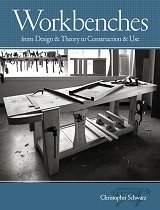
Workbenches: From Design & Theory to Construction & Use
by Christopher Schwarz (signed)
Publisher: Popular Woodworking Books
Pub. Date: November, 2007
ISBN-13: 978-1558708402
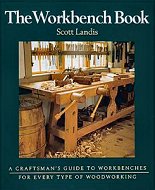
by Scott Landis
Publisher: Taunton Press
Pub. Date: September, 1998
ISBN-13: 978-1561582709
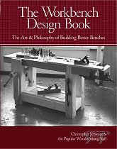
The Workbench Design Book
by Christopher Schwarz (signed)
Publisher: Popular Woodworking Books
Pub. Date: November, 2010
ISBN-13: 978-1440310409
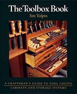
by Jim Tolpin
Publisher: Taunton Press
Pub. Date: September, 1998
ISBN-13: 978-1561582723

Roman Workbenches
Letterpress Edition
by Christopher Schwarz (signed)
Publisher: Lost Art Press
Pub. Date: April, 2017
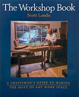
by Scott Landis
Publisher: Lost Art Press
(orig. Taunton Press, 1991)
Pub. Date: January, 2021
ISBN-13: 978-1954697003
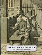
Ingenious Mechanicks: Early Workbenches & Workholding
by Christopher Schwarz
Publisher: Lost Art Press
Pub. Date: January, 2018
ISBN-13: 978-0997870725
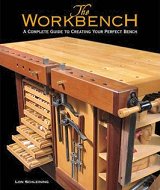
by Lon Schleining
Publisher: Taunton Press
Pub. Date: October, 2004
ISBN-13: 978-1561585946
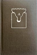
The Anarchist's Workbench (PDF)
by Christopher Schwarz
Publisher: Lost Art Press
Pub. Date: June, 2020
ISBN-13: 978-1733391658
DVD with measured drawings
by Mike Siemsen
Publisher: Lost Art Press
Pub. Date: August, 2014
↑
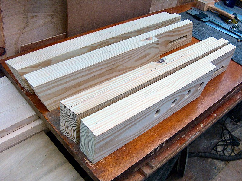
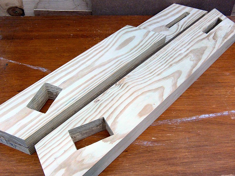
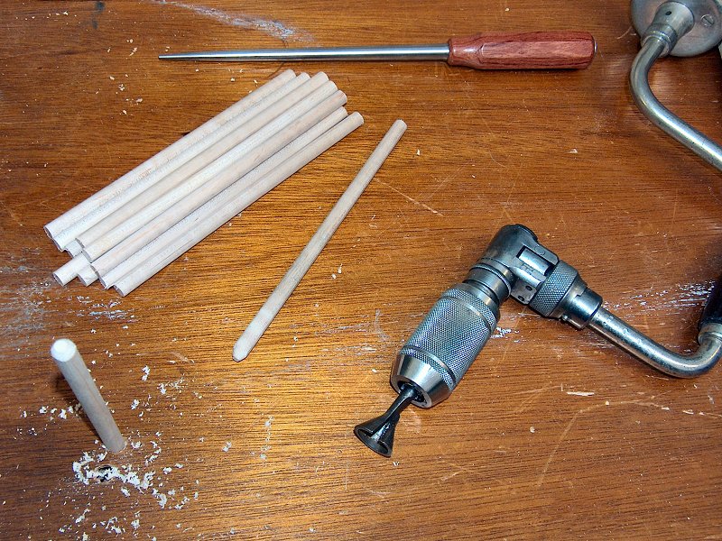
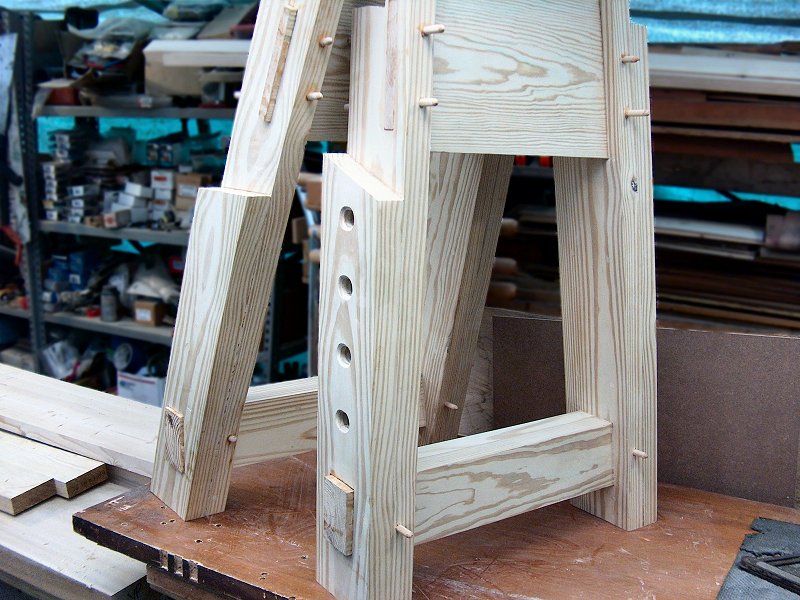
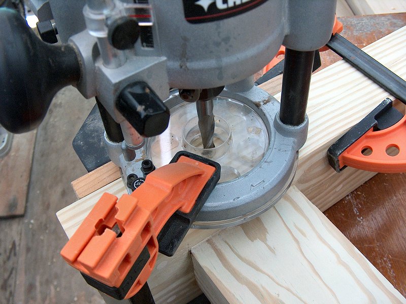
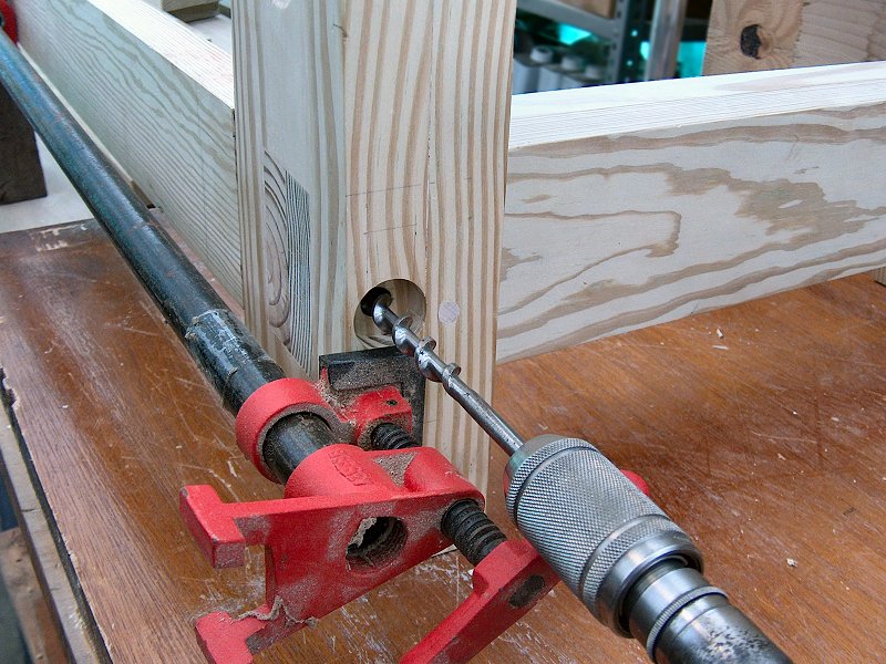
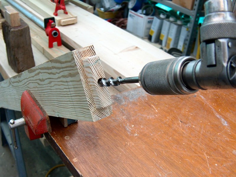
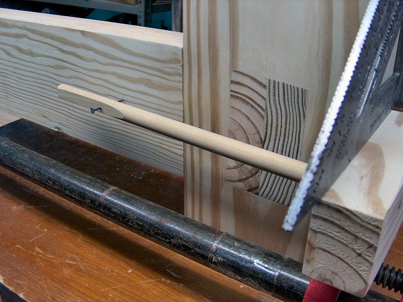
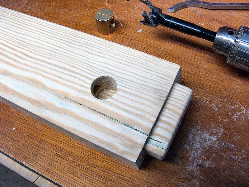
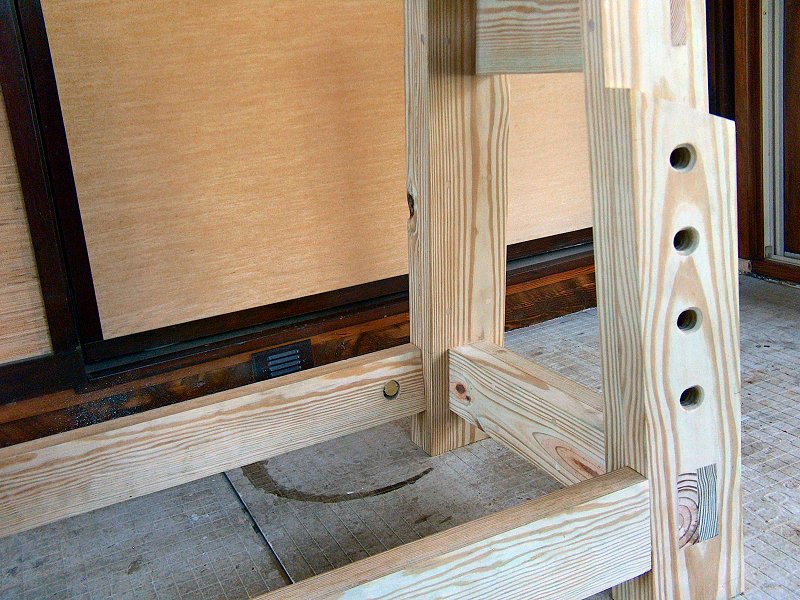
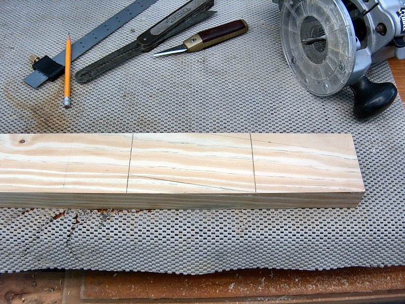
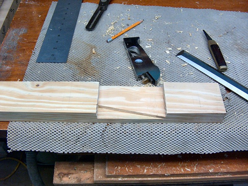
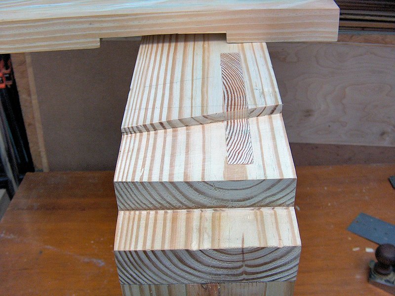
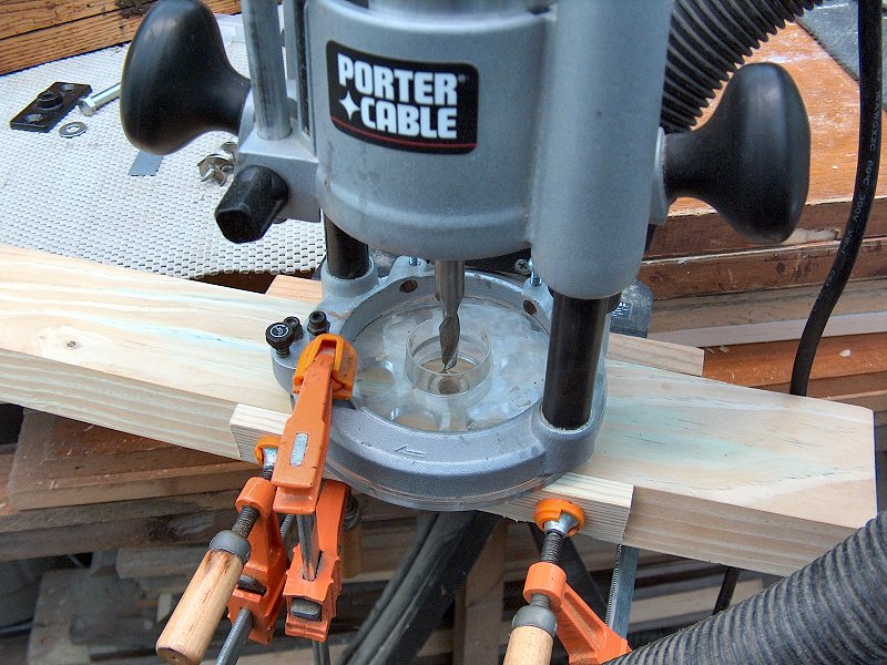
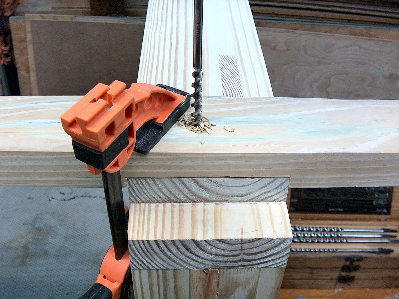
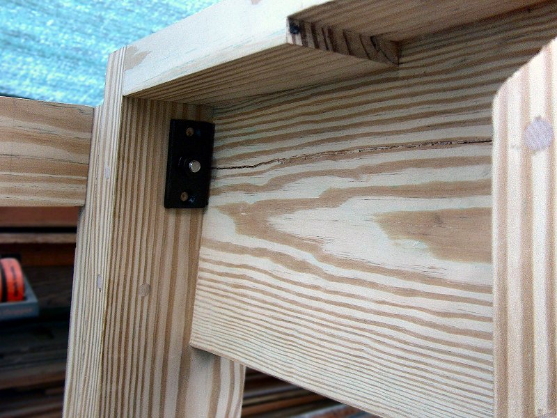
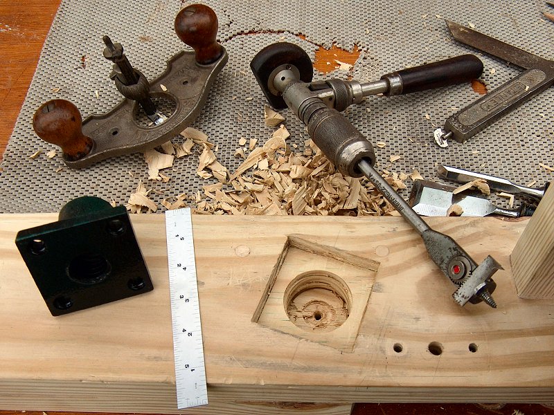
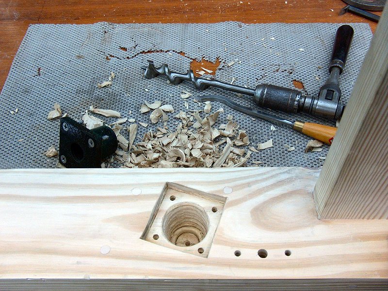
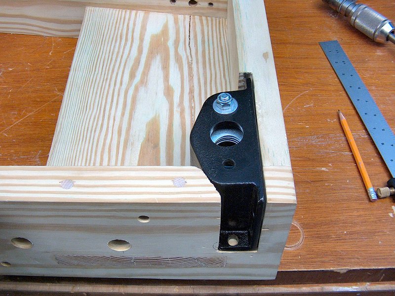
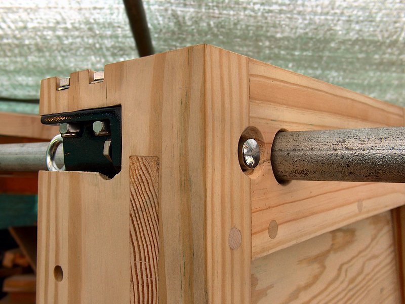
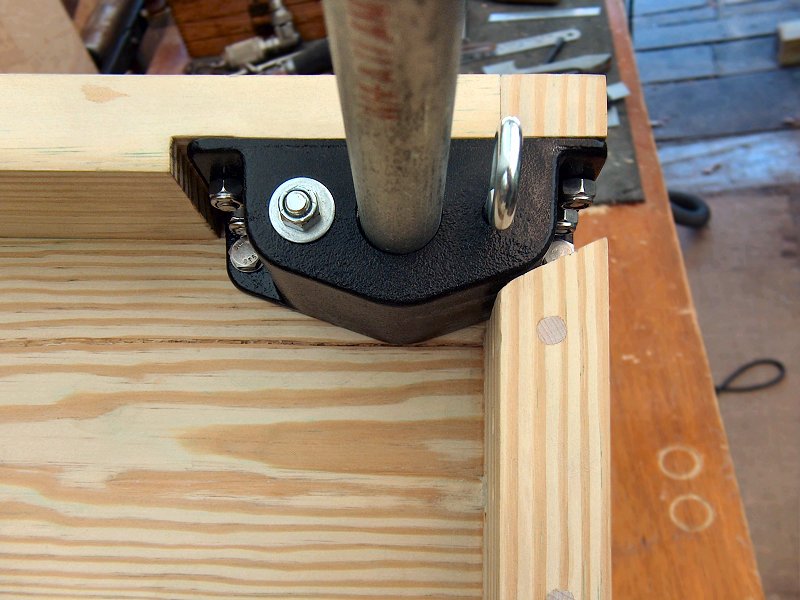
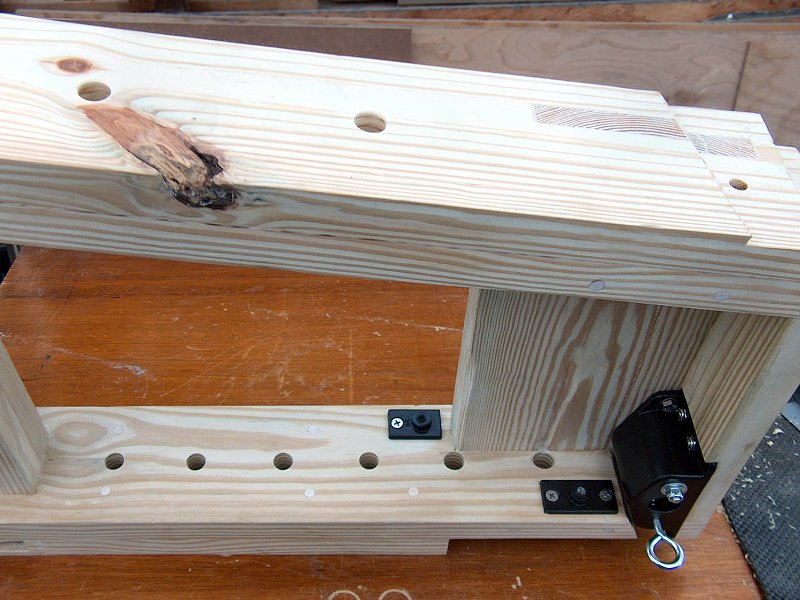
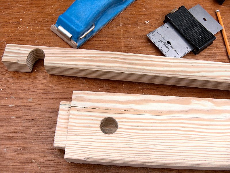
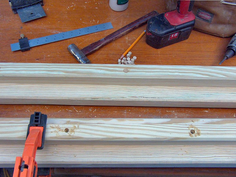
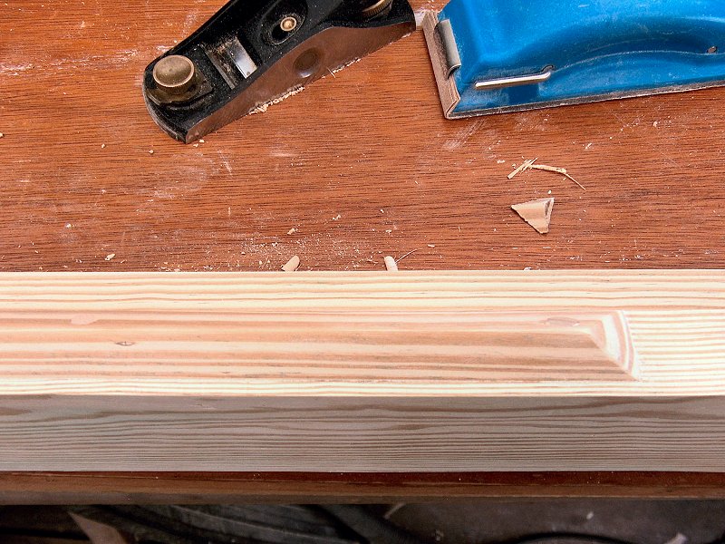
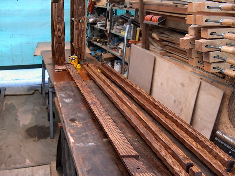
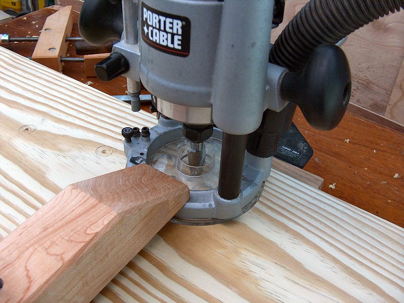
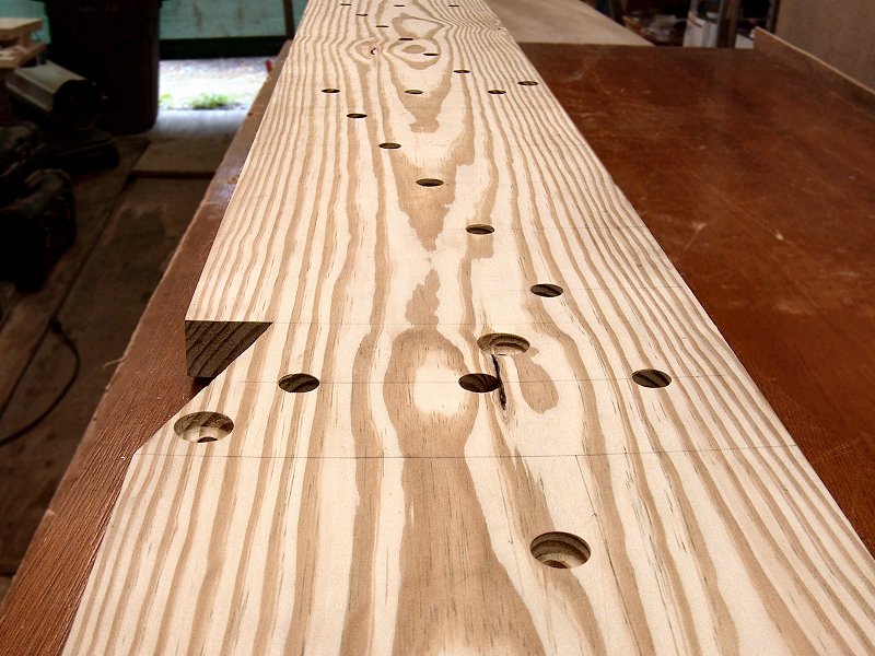
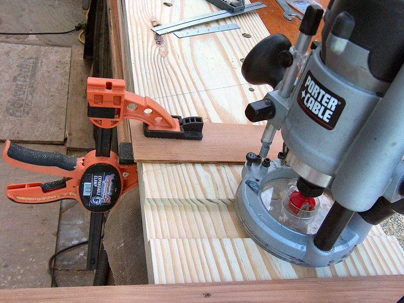
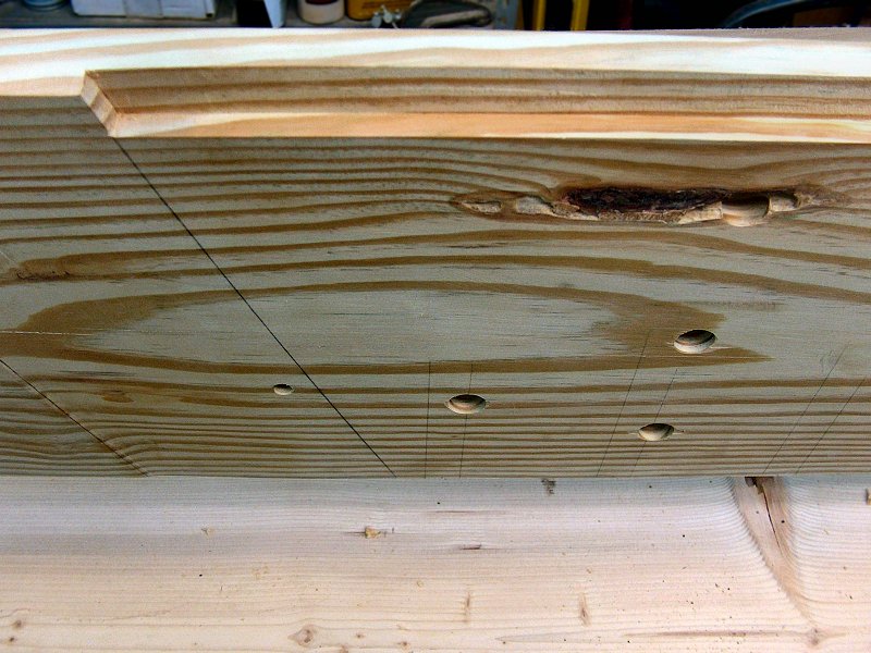
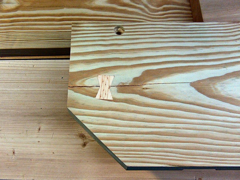
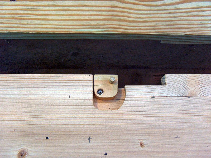
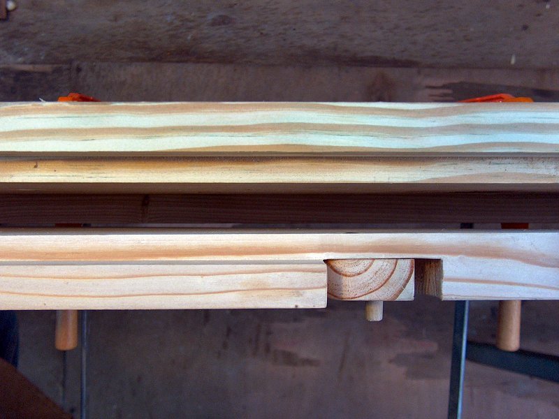
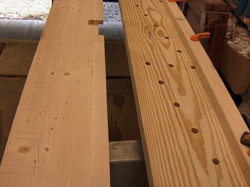
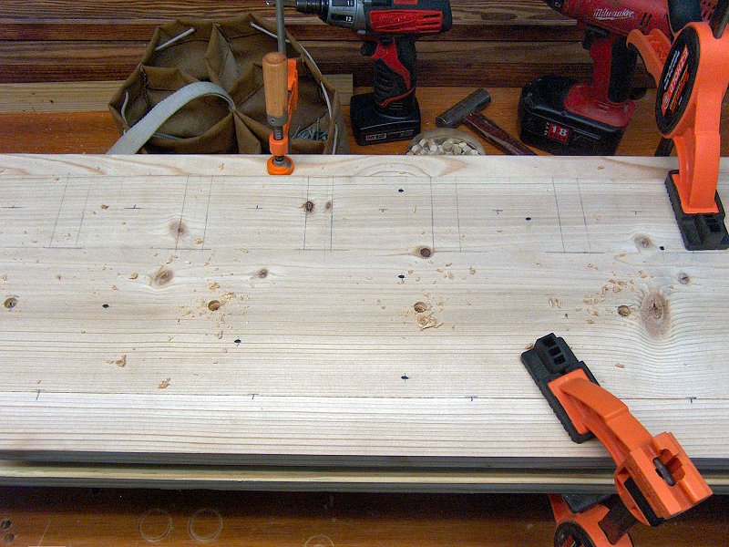
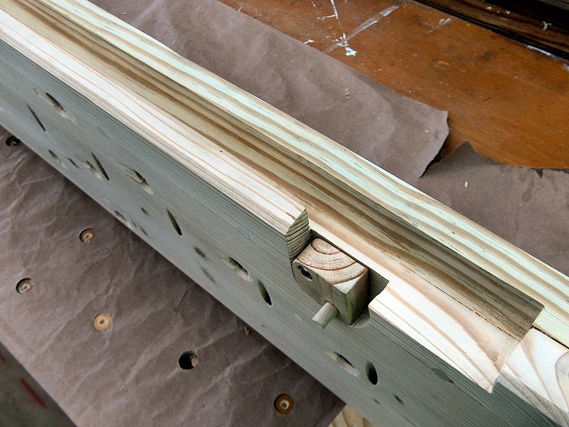
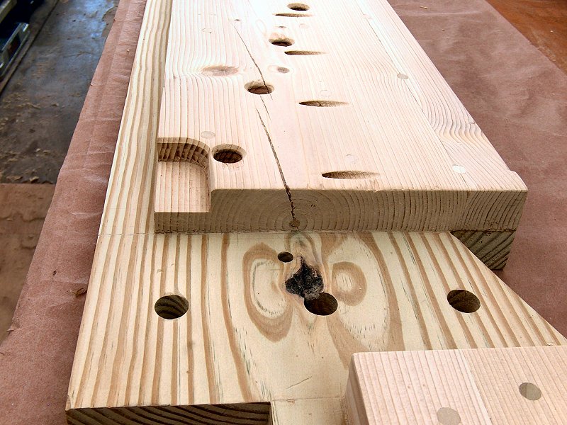
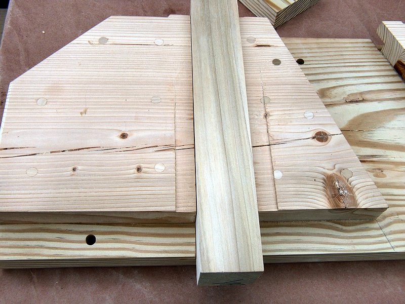
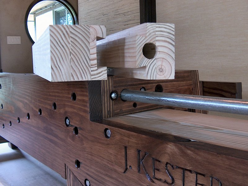
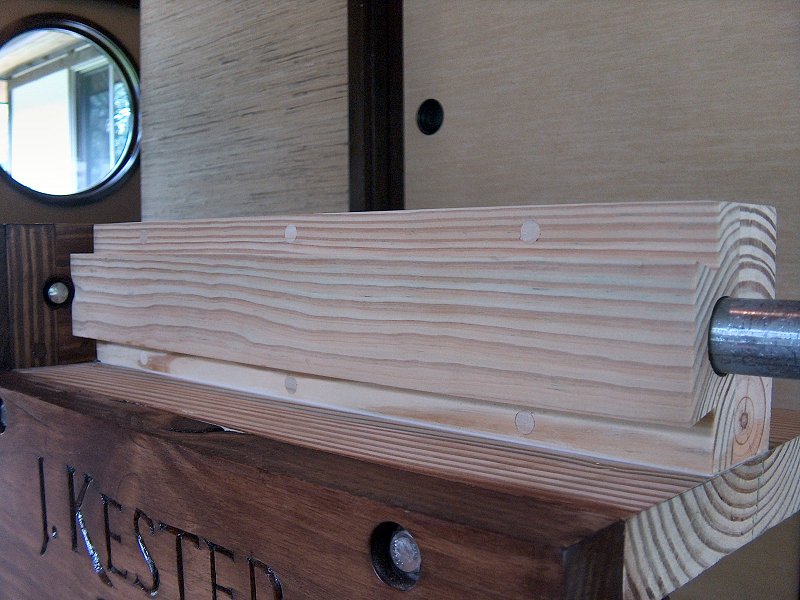
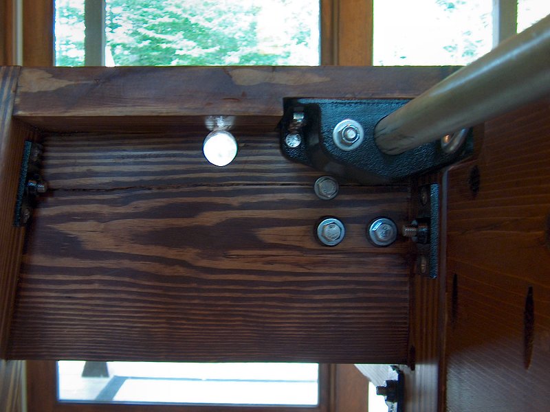
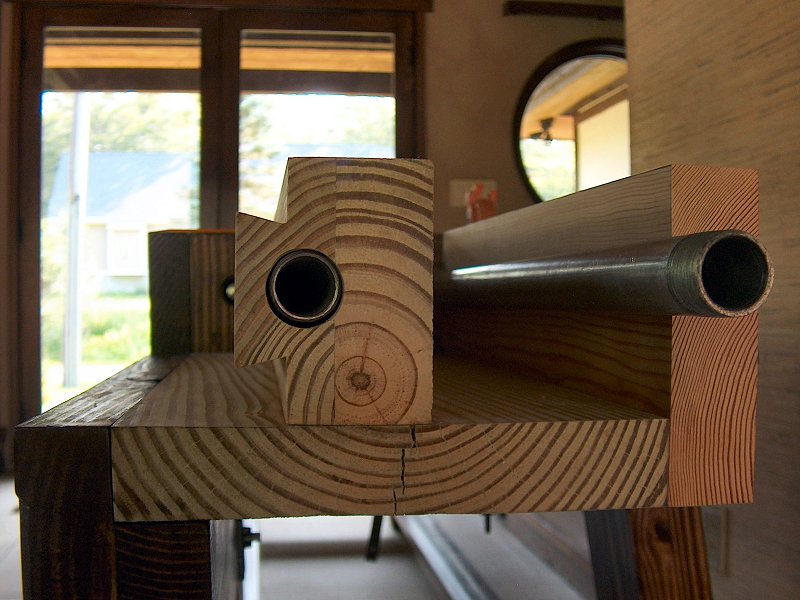
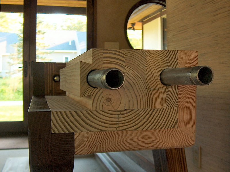
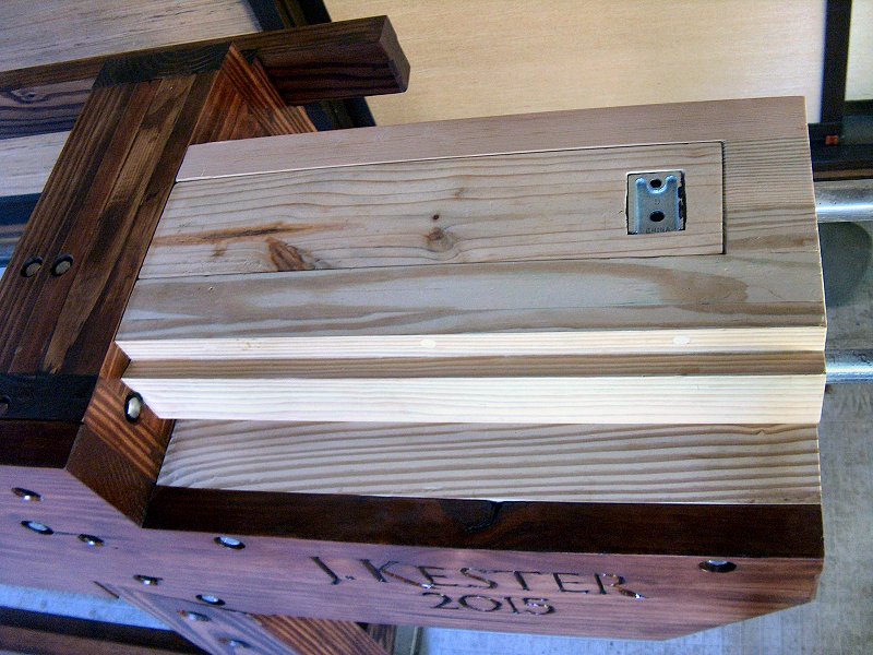
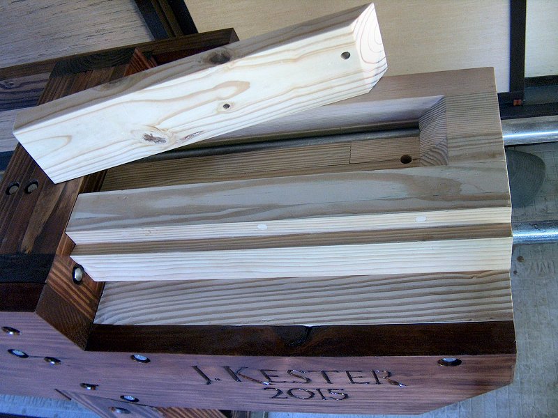
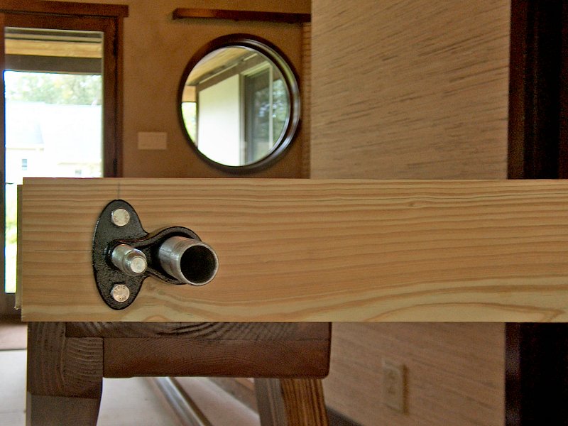
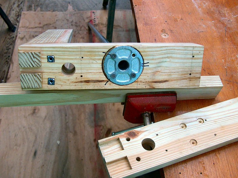
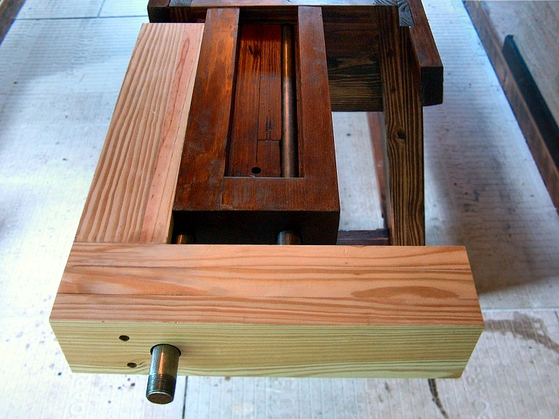
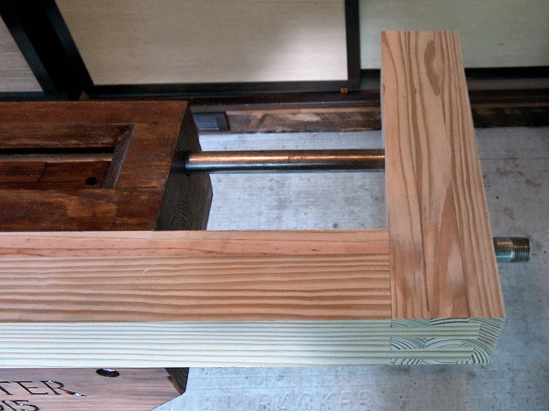
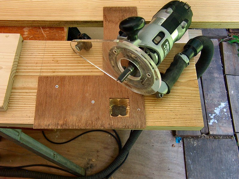
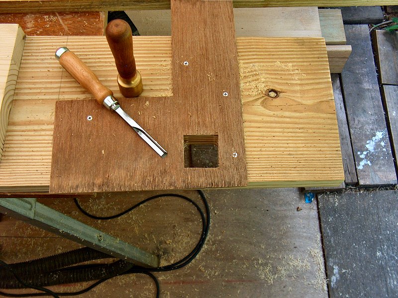
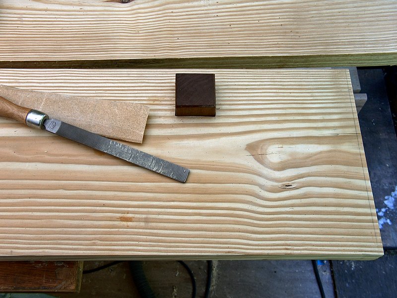
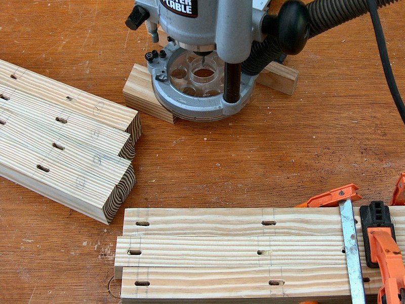
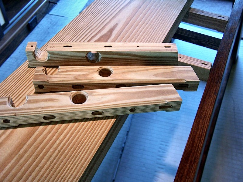
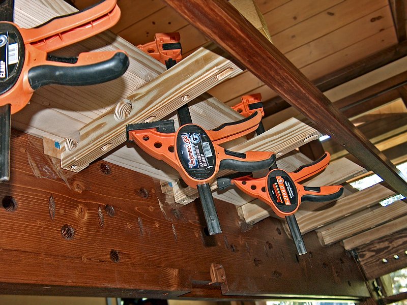
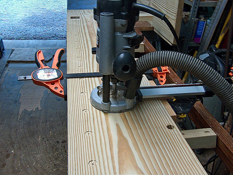
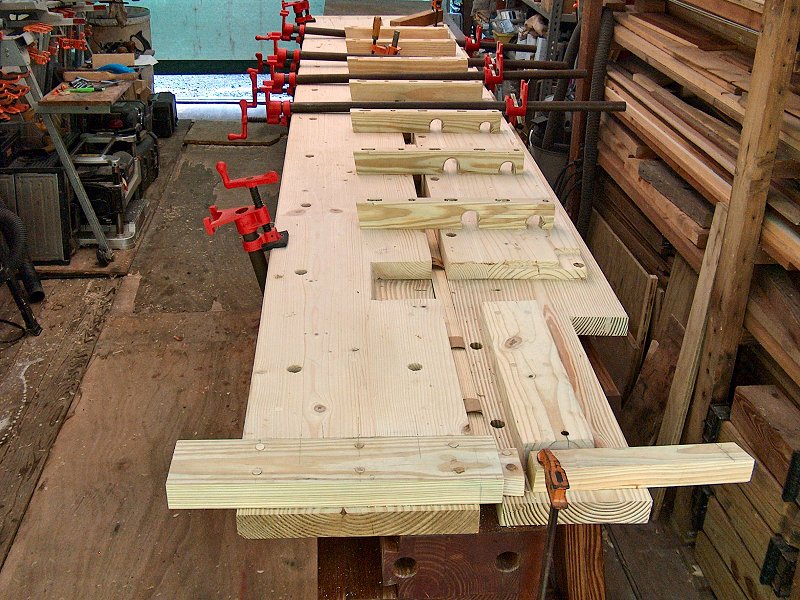
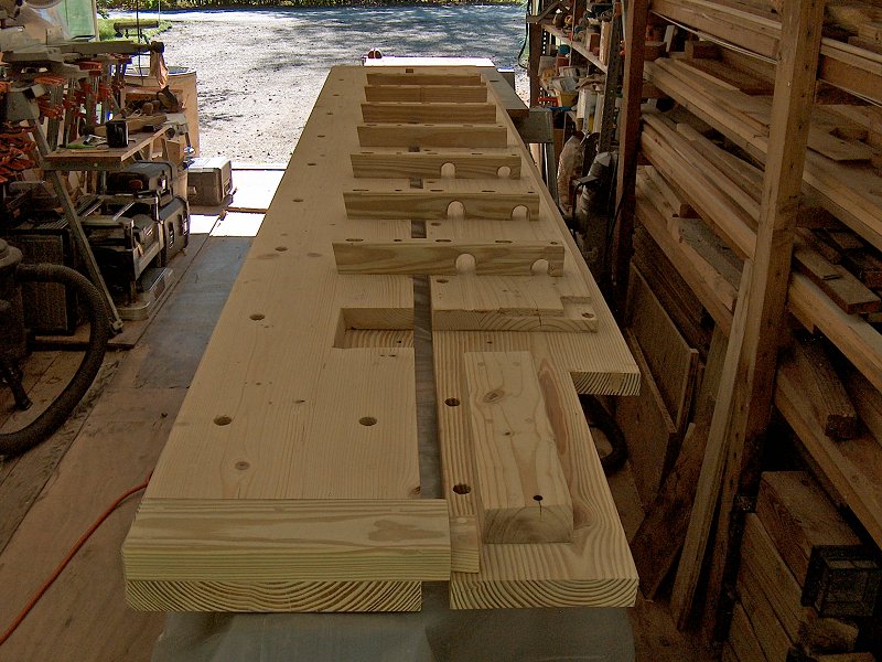
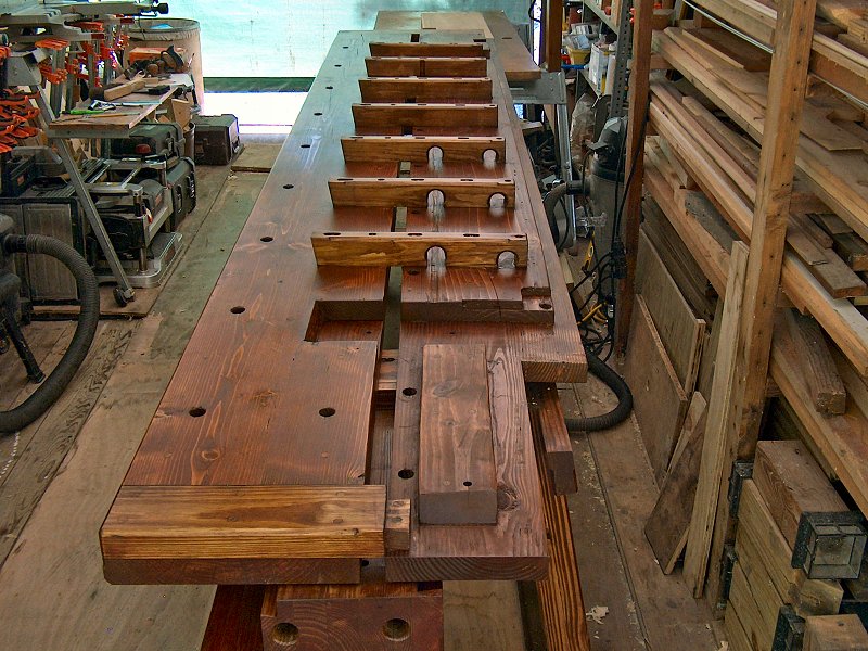
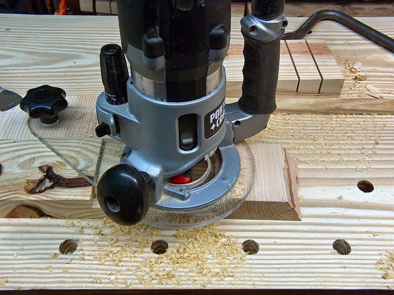
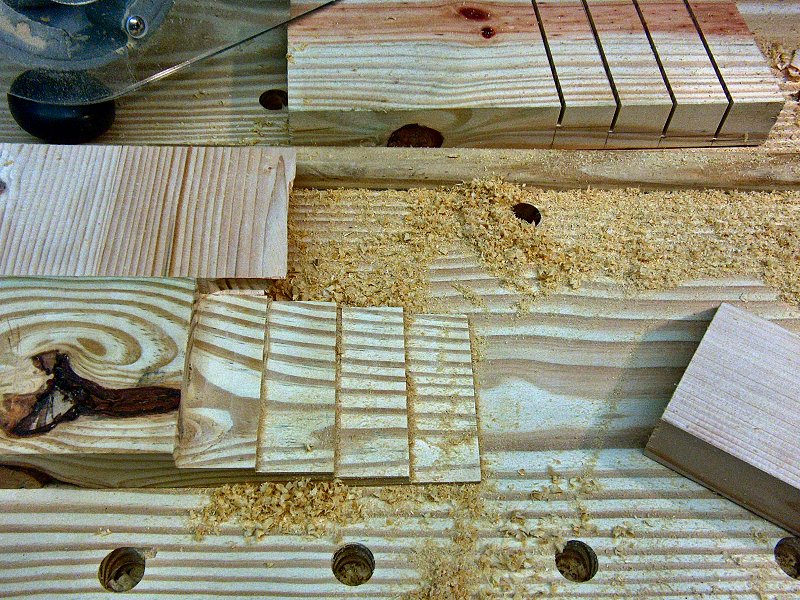
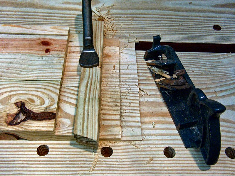
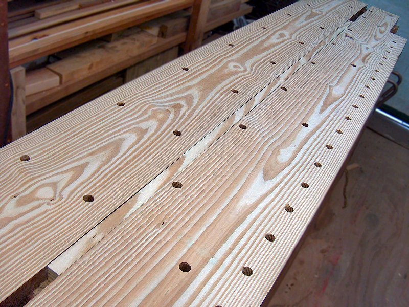
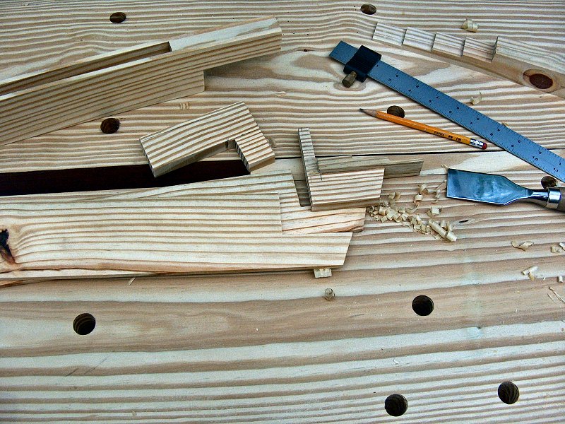
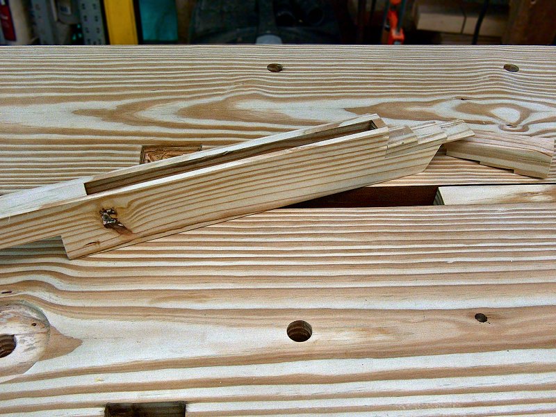
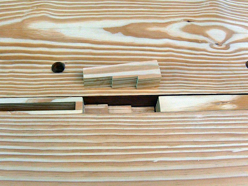
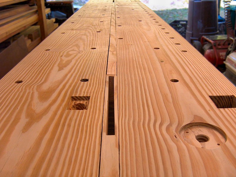
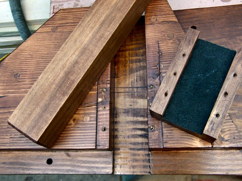
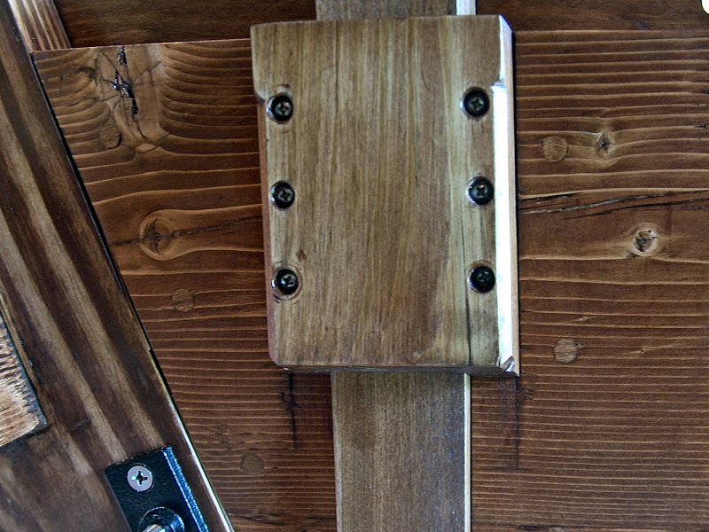
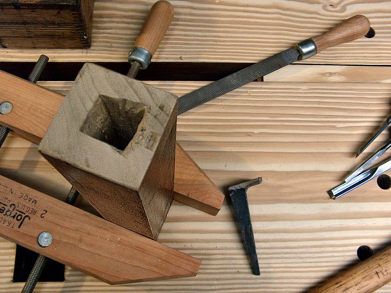
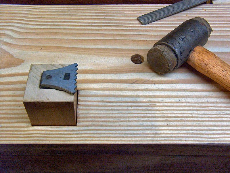
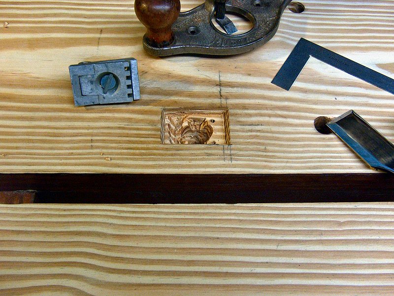
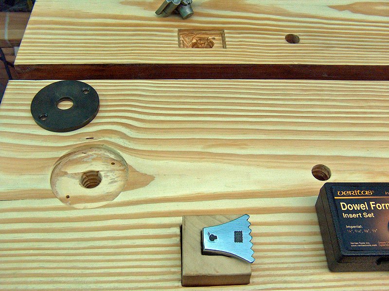
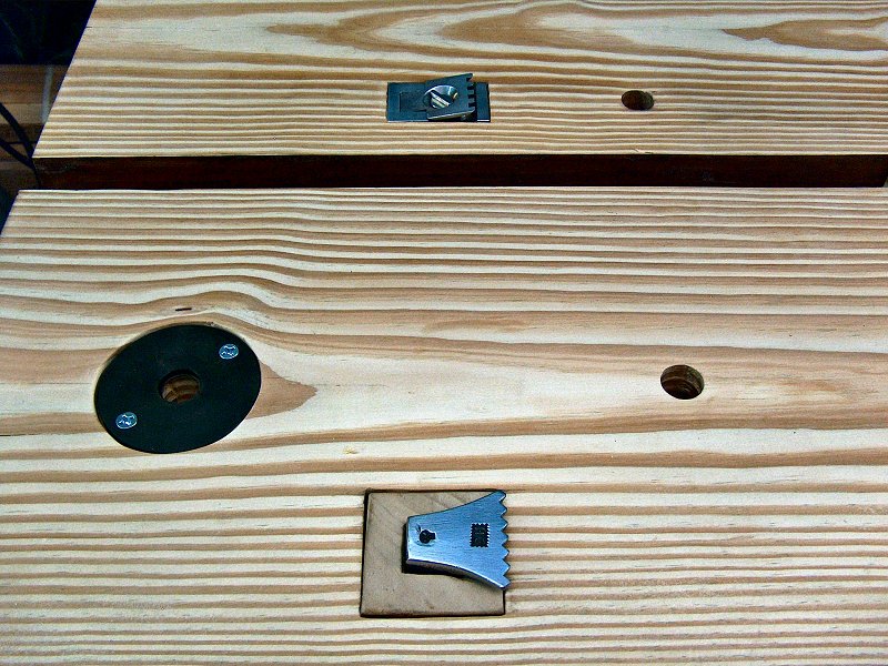
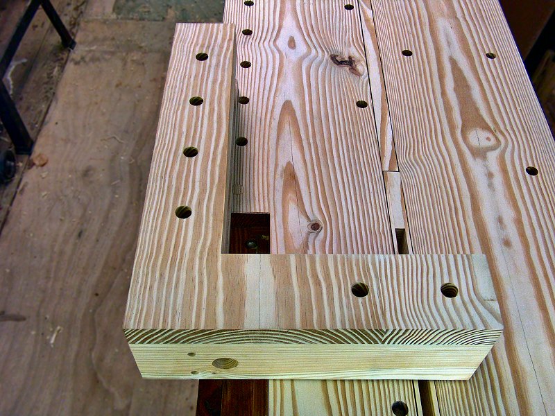
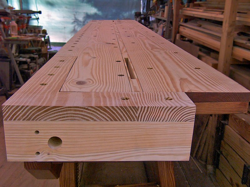
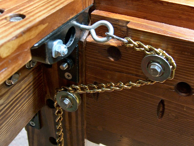
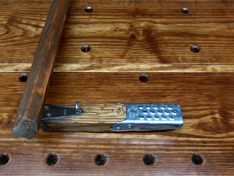
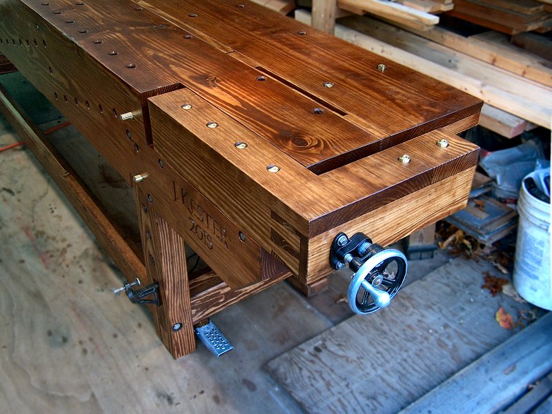
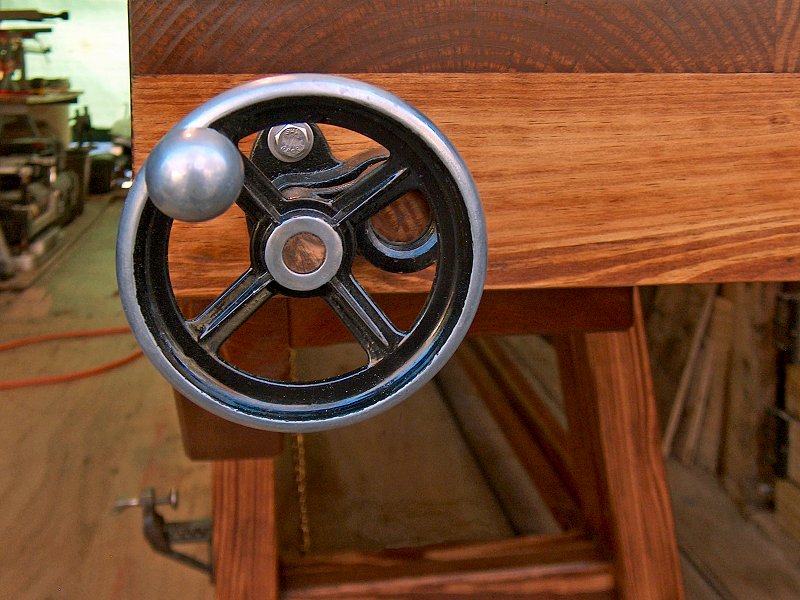
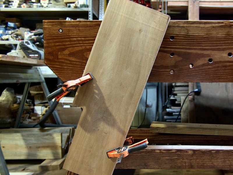
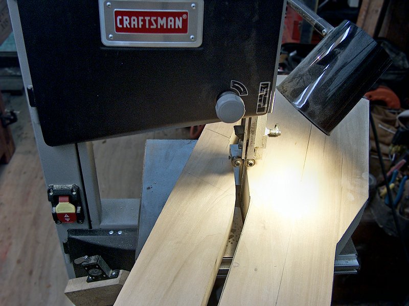
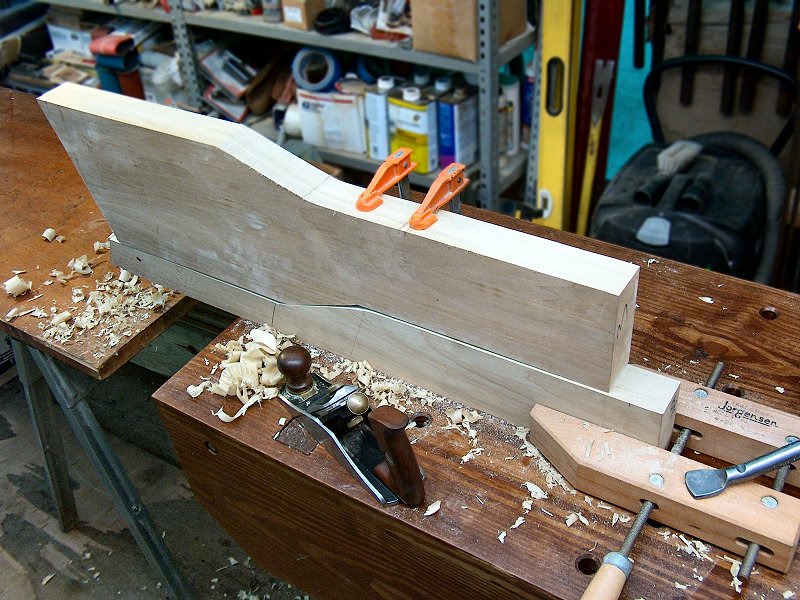
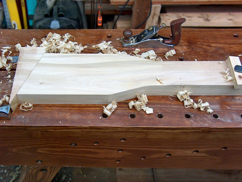
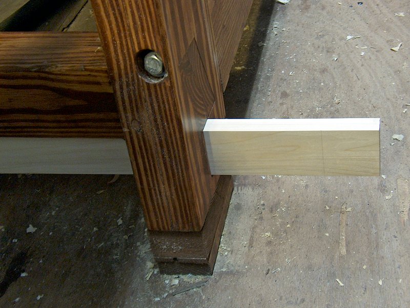
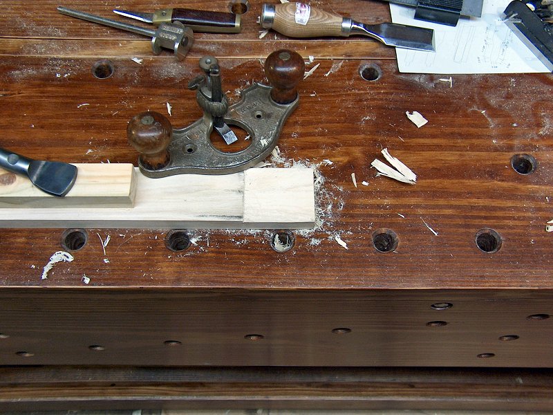
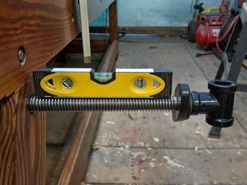
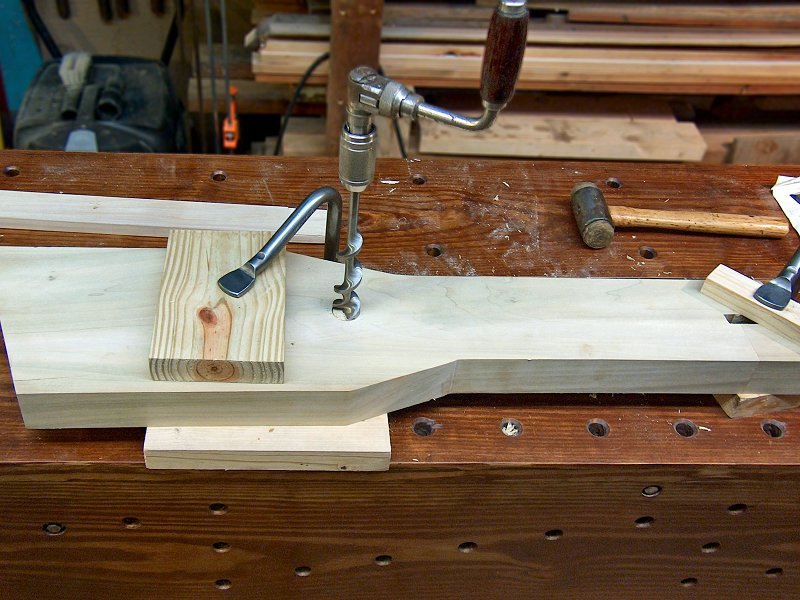
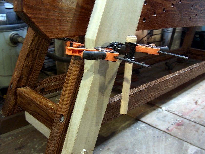
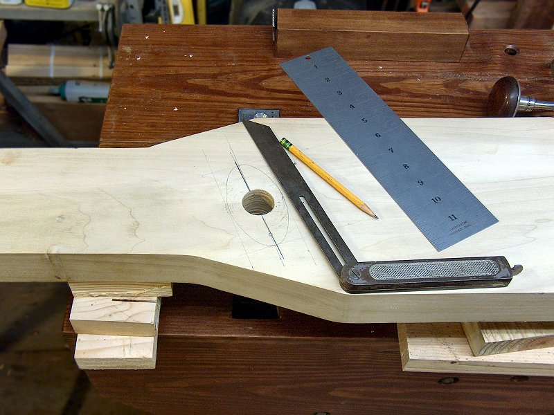
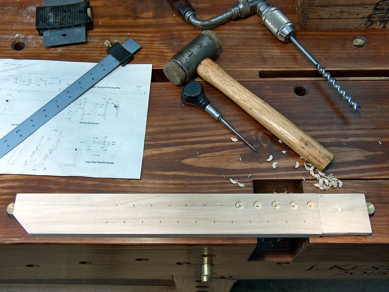
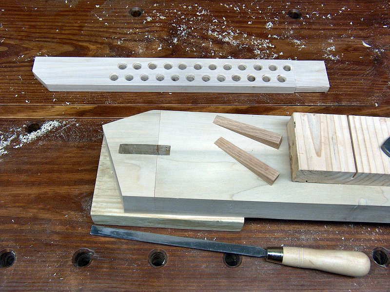
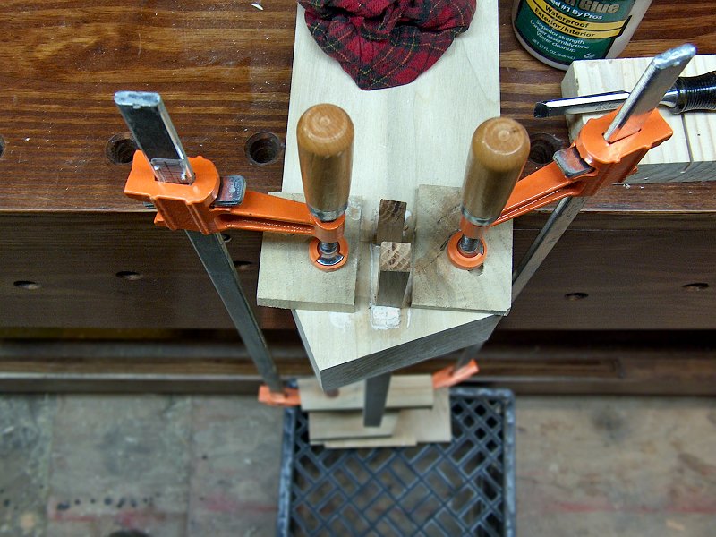
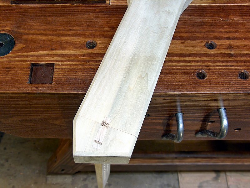
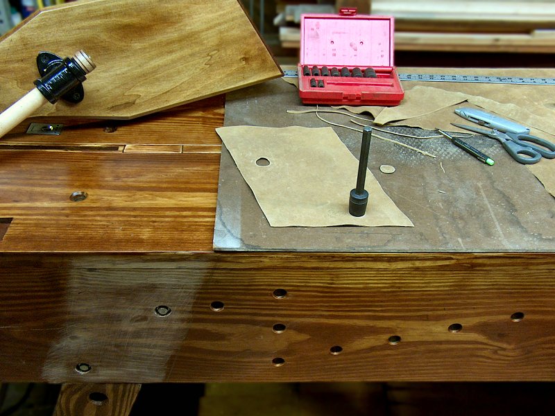
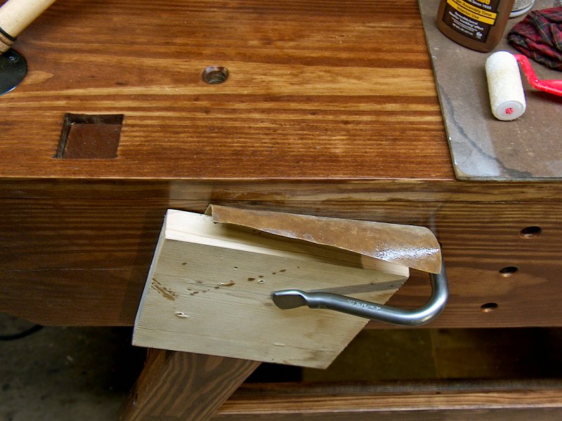
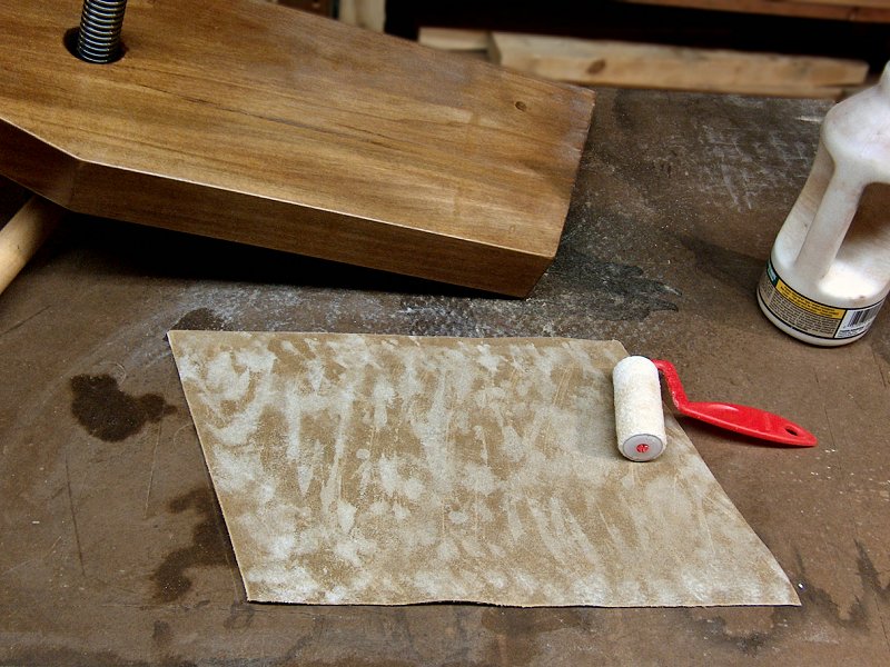
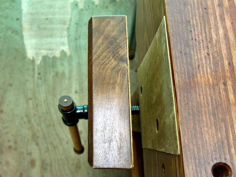
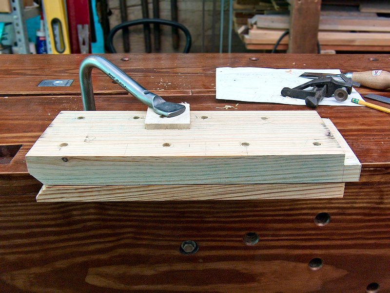
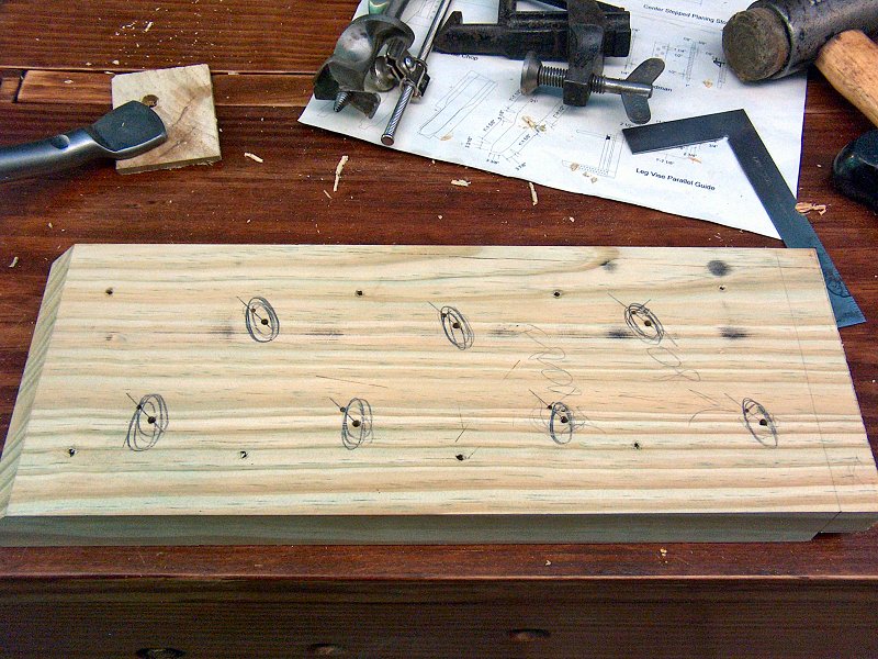
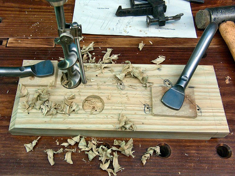
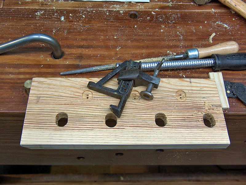
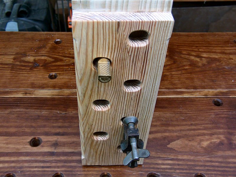
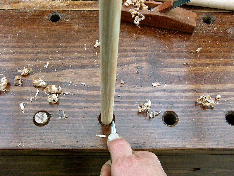
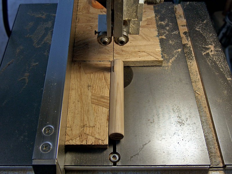
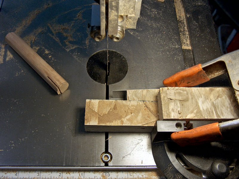
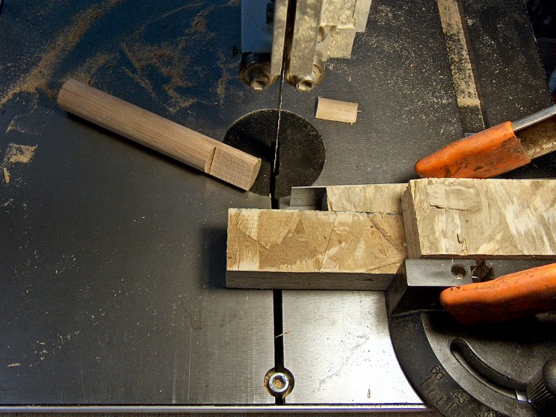
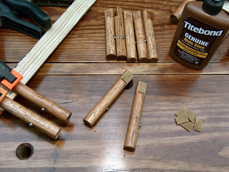
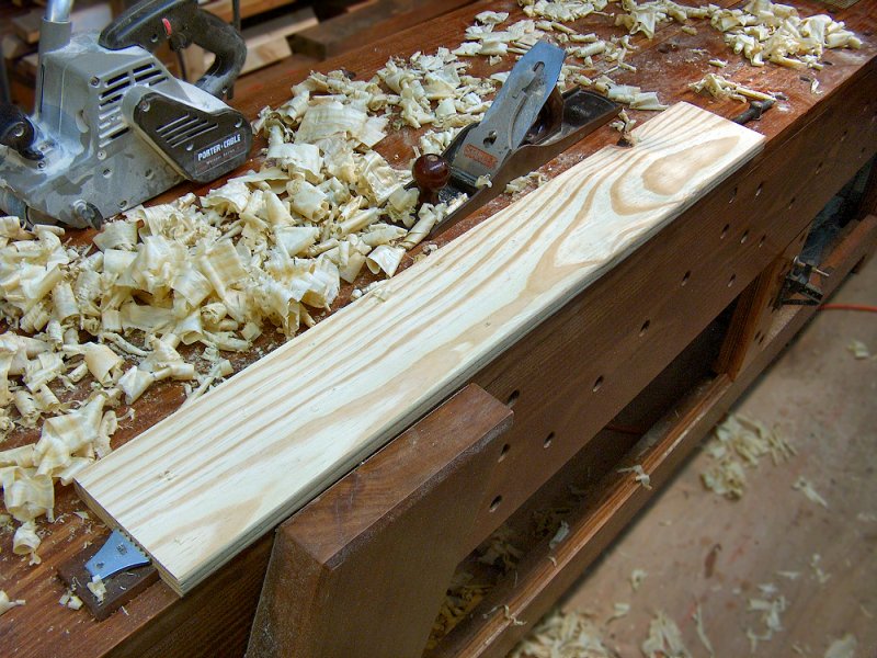
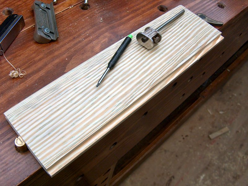
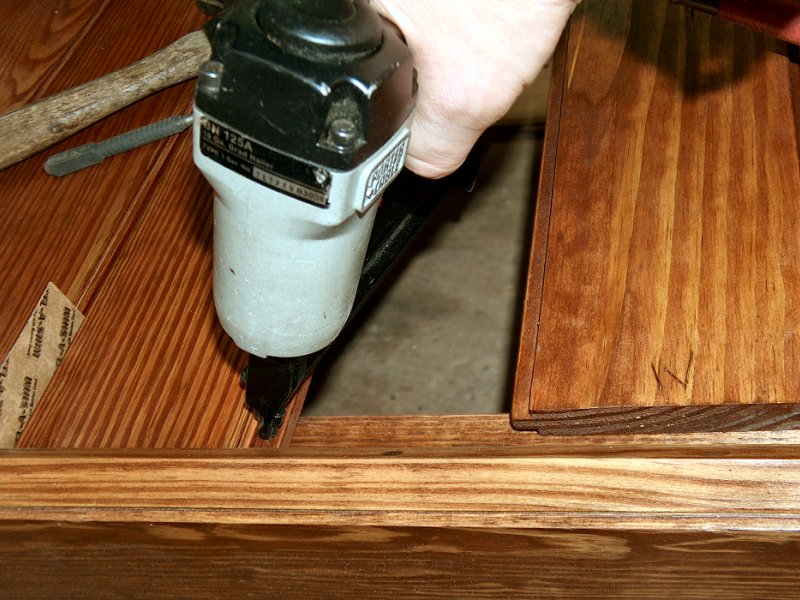
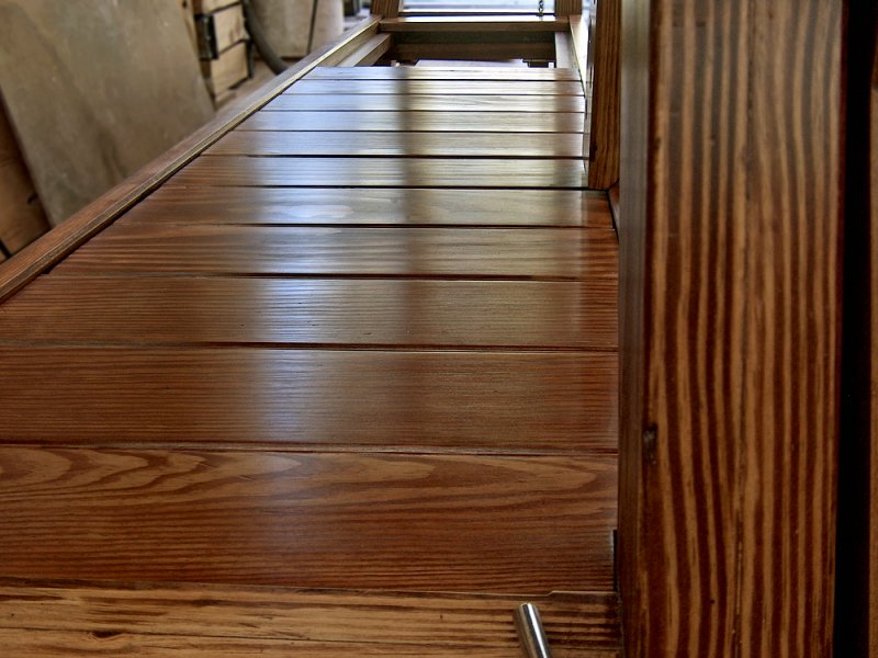
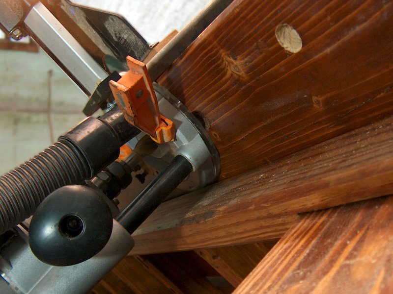
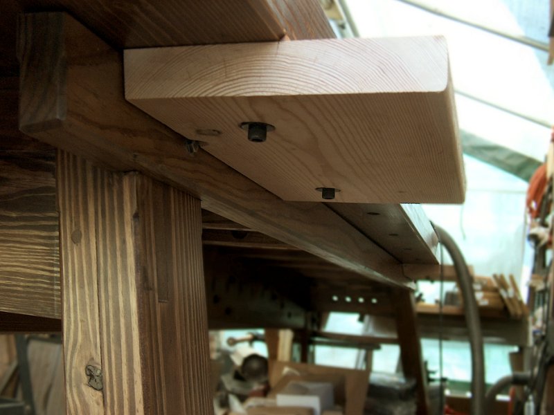
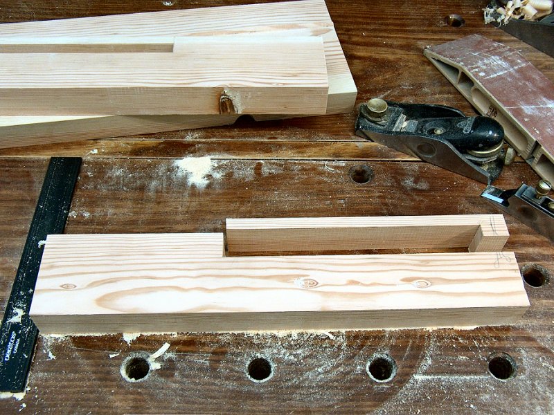
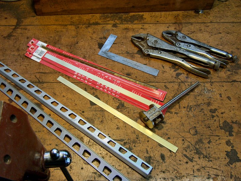
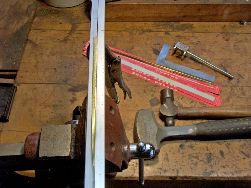
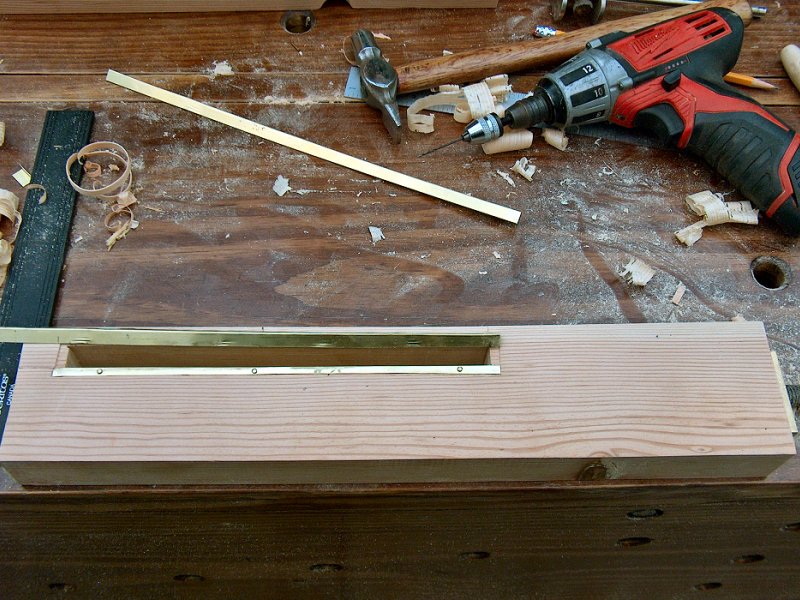
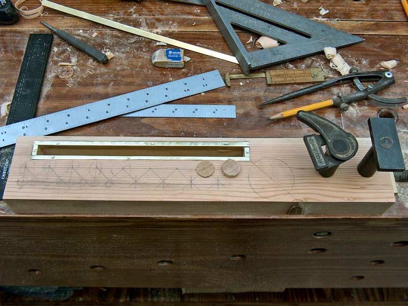
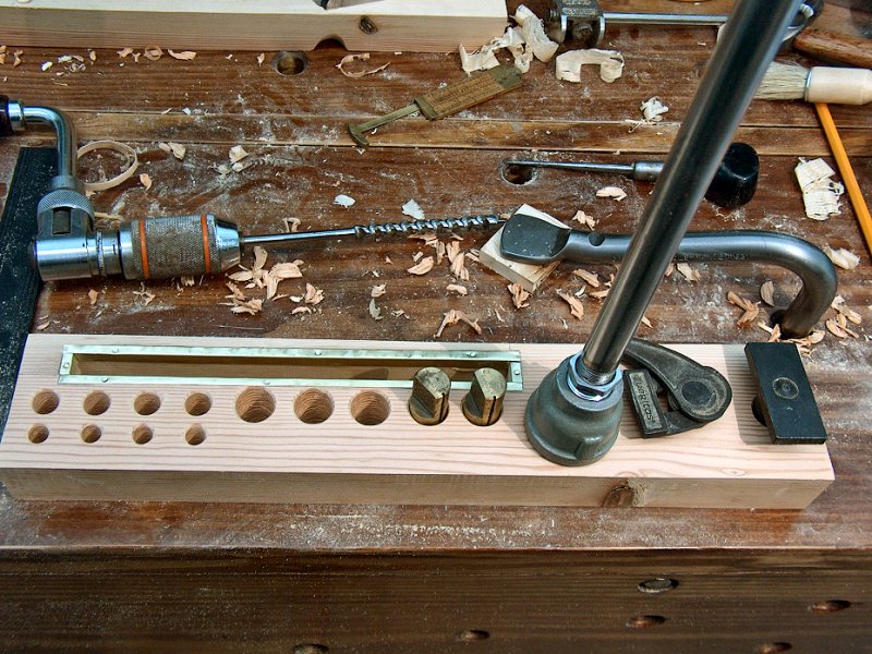
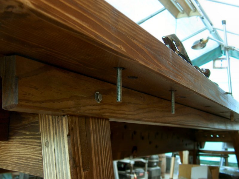
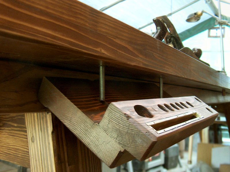
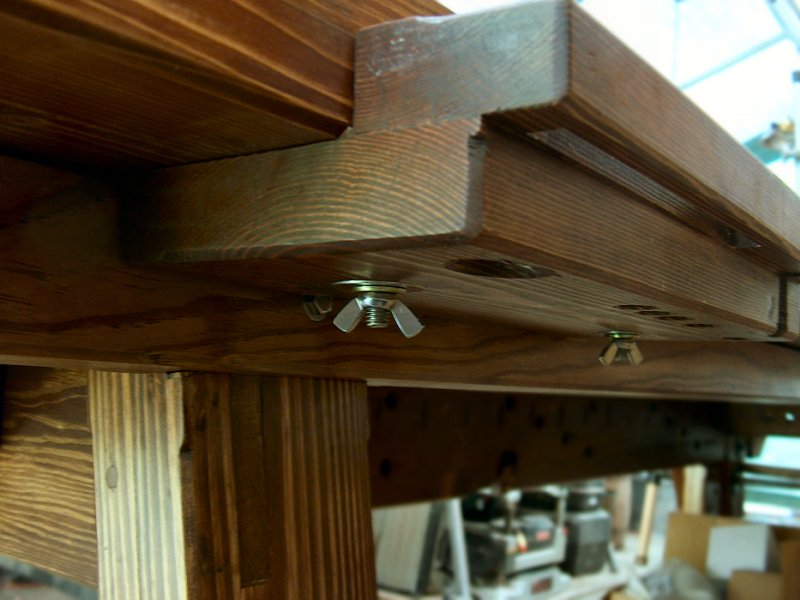
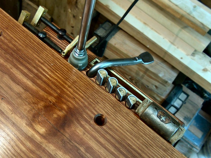
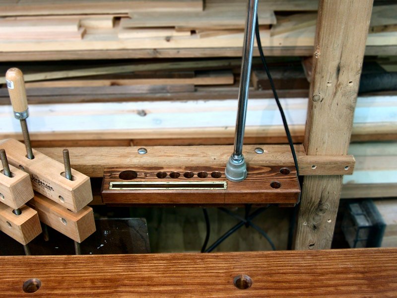
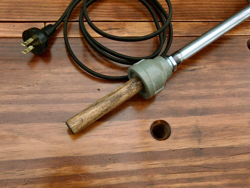
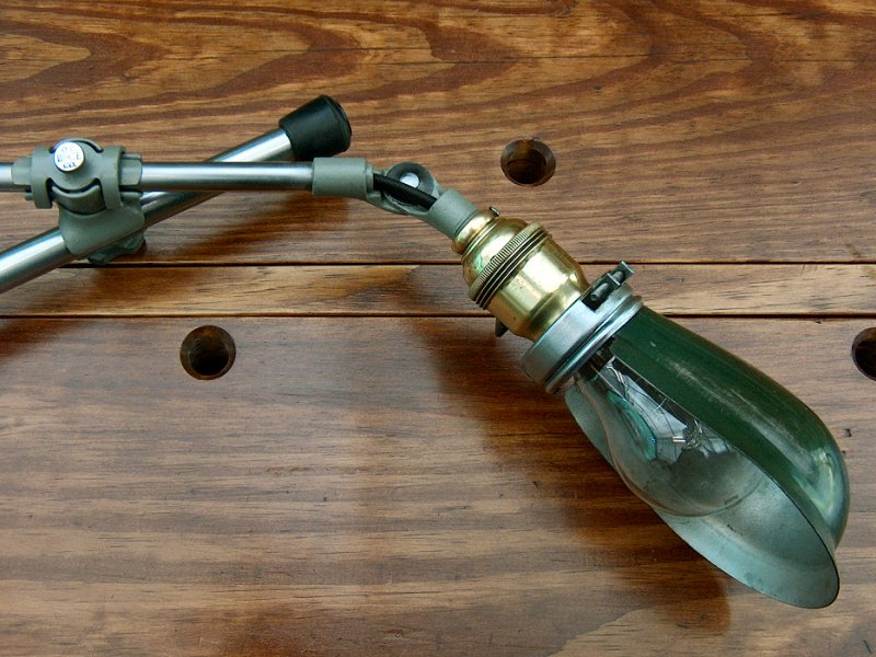
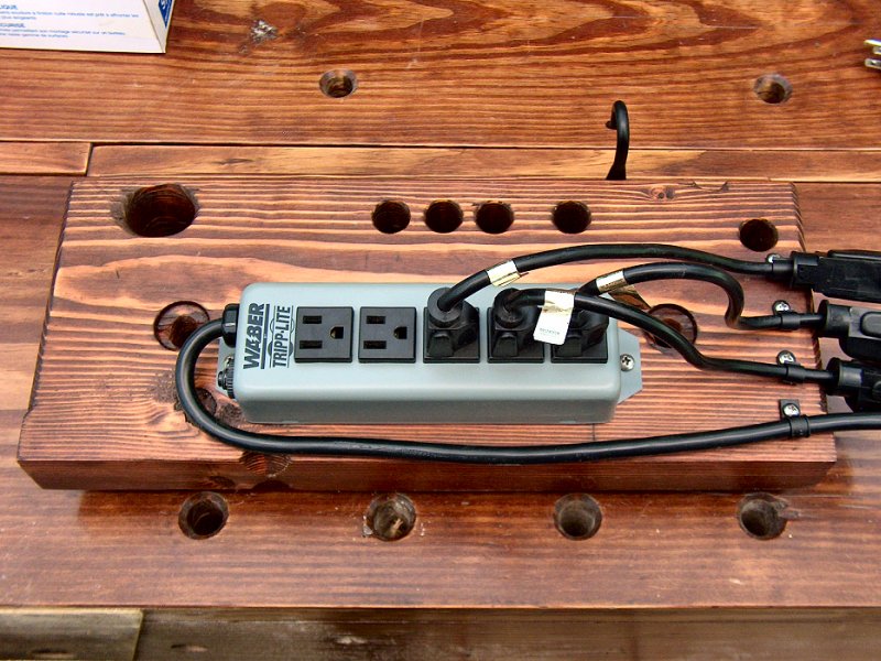
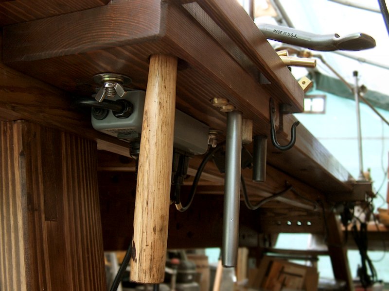
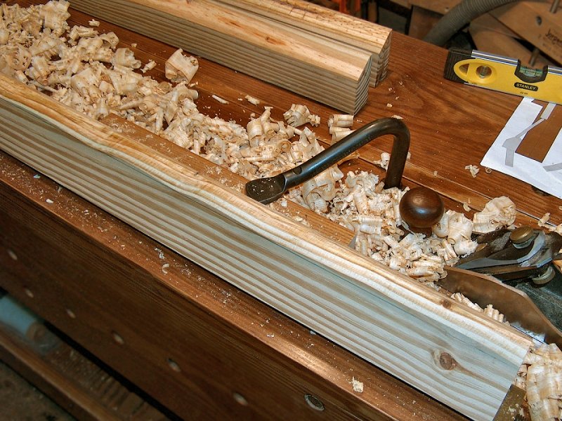
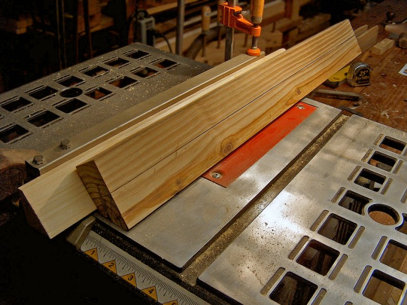
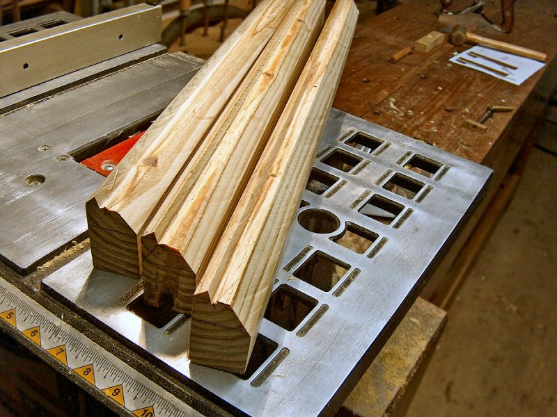
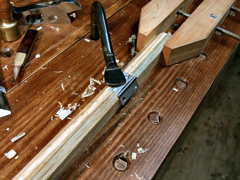
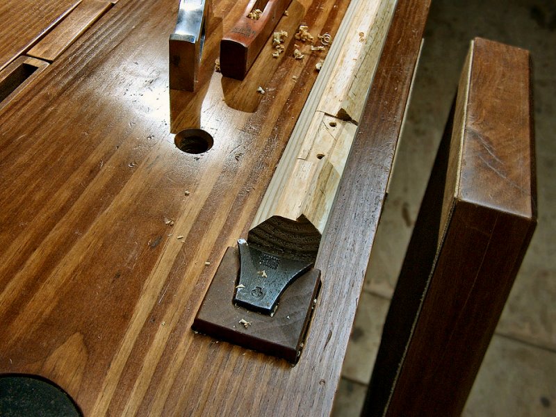
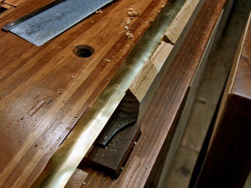
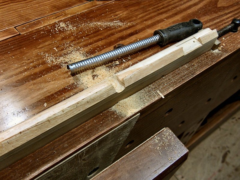
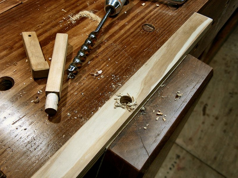
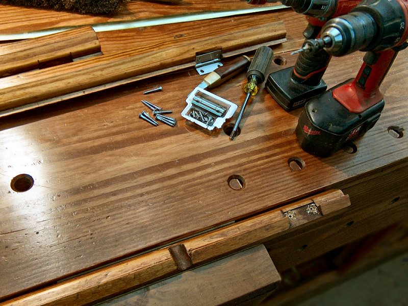
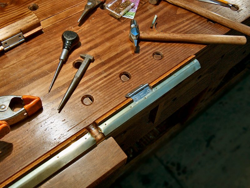
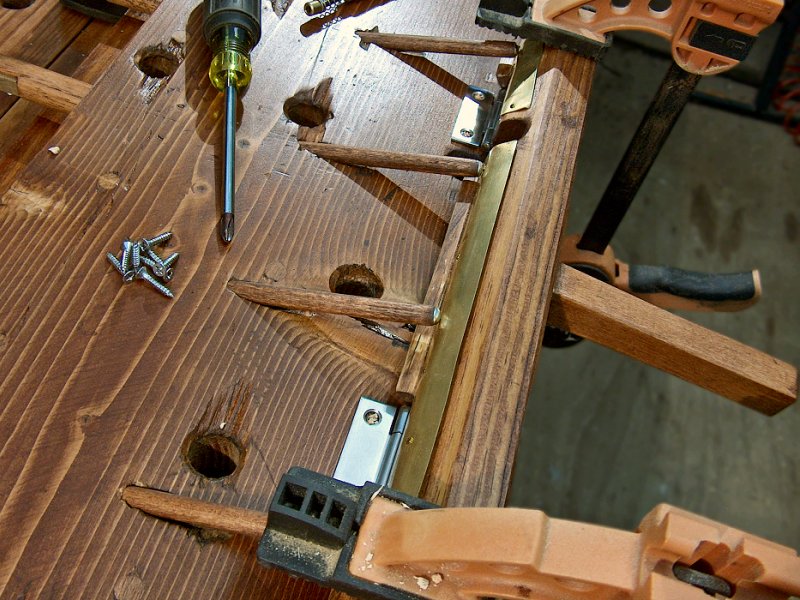
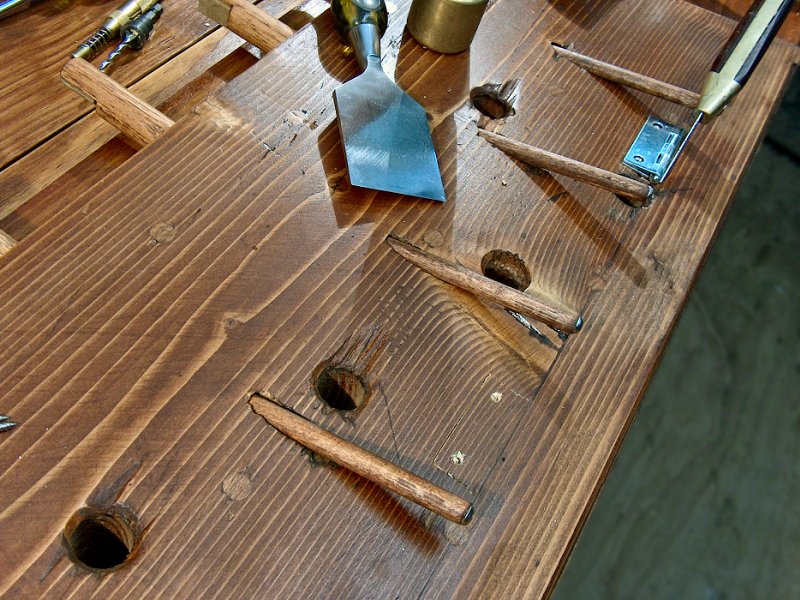
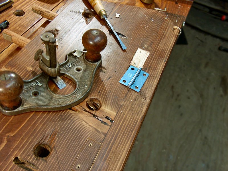
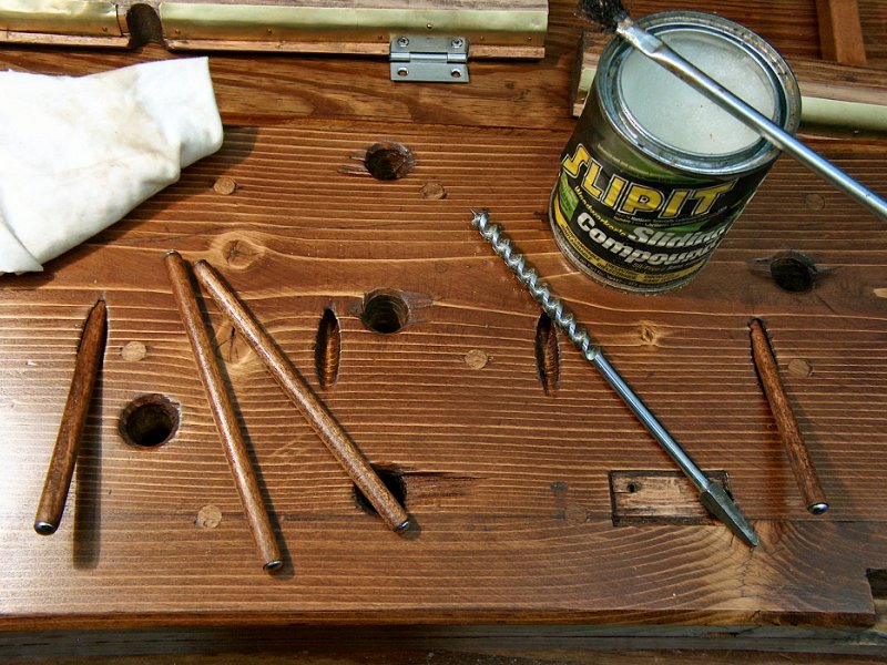
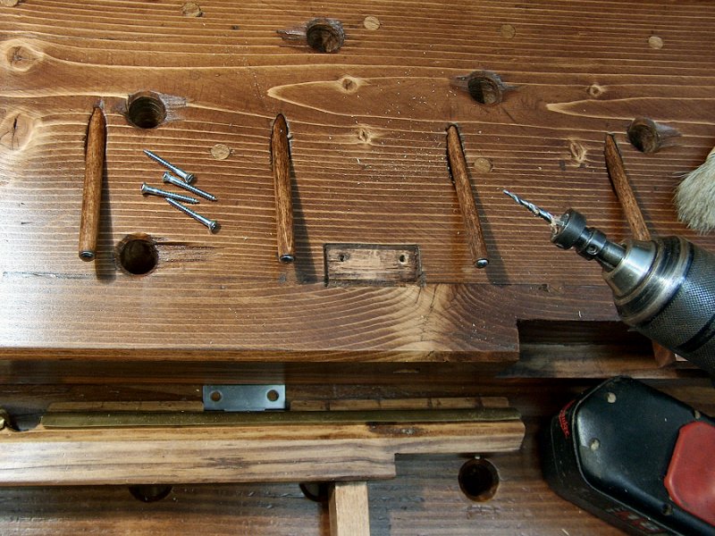
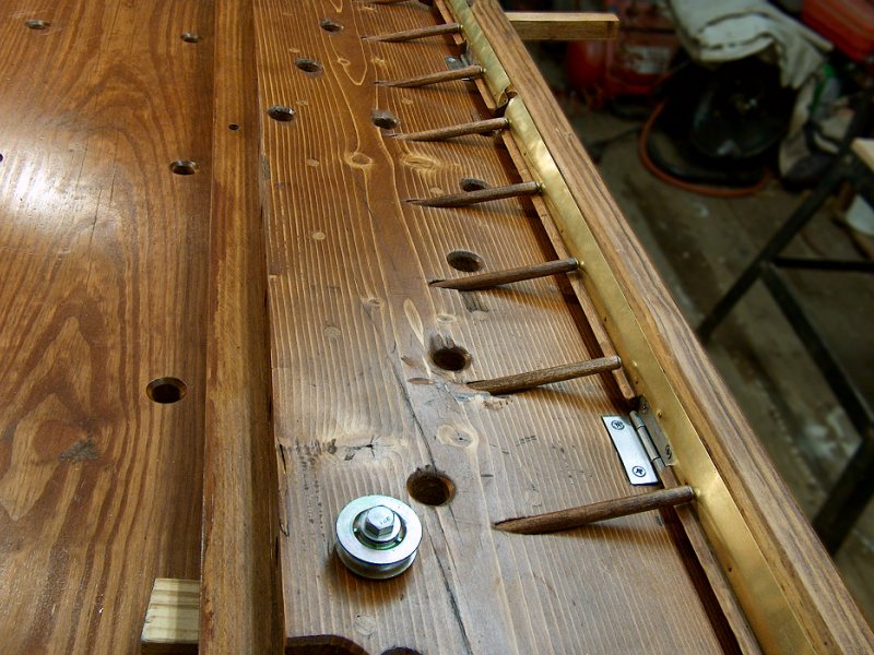
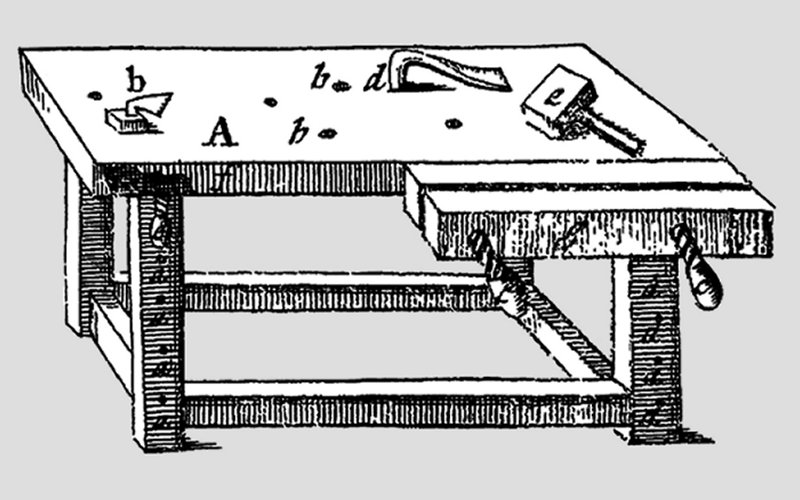
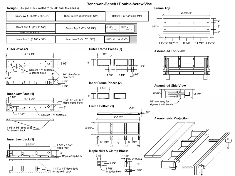
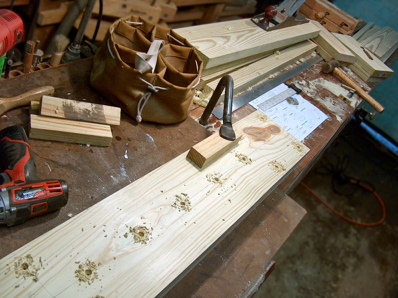
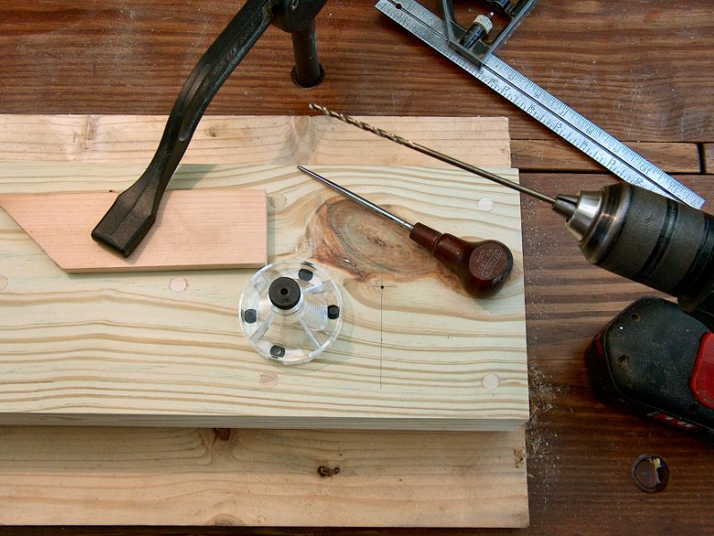
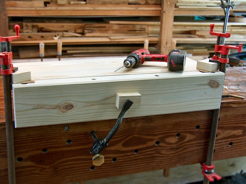
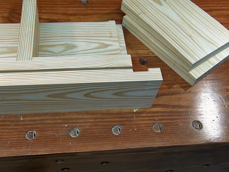
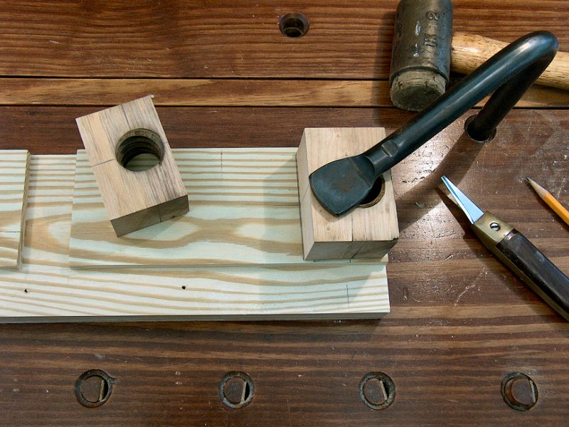
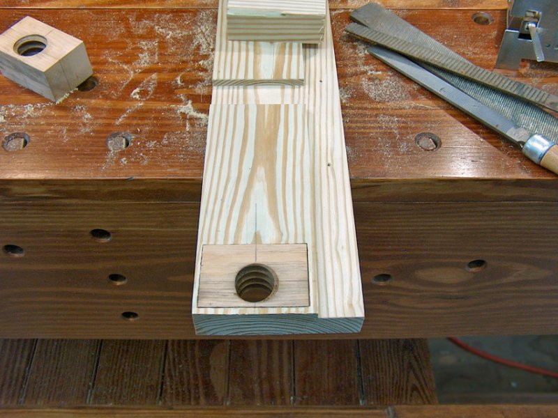
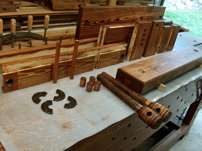
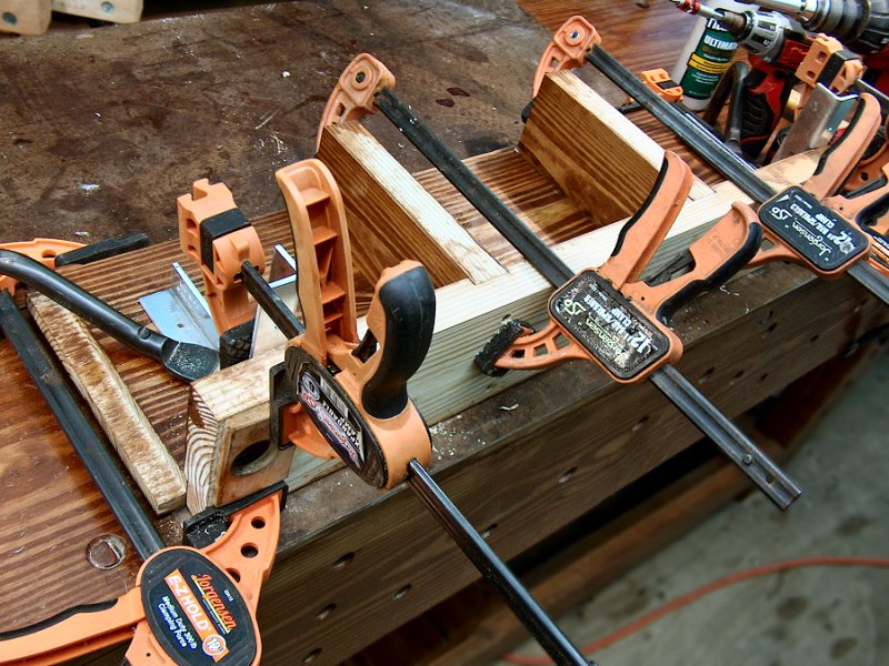
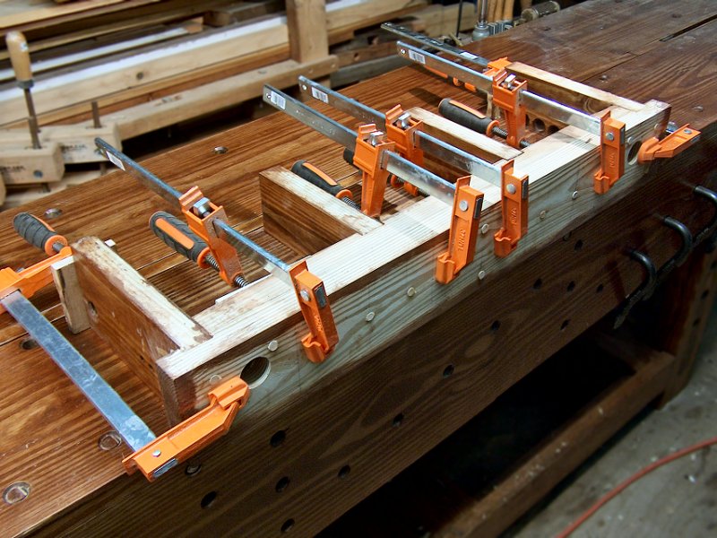
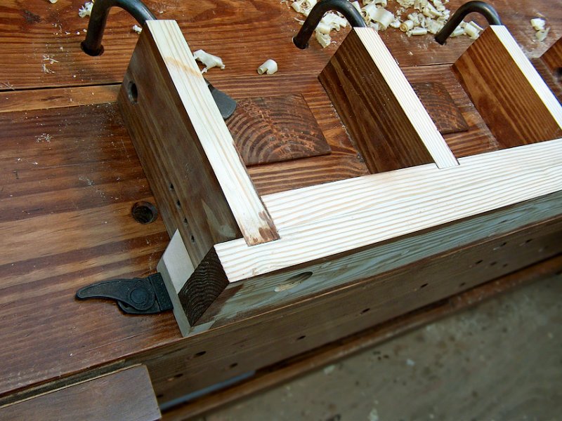
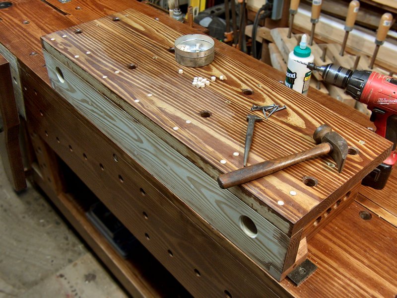
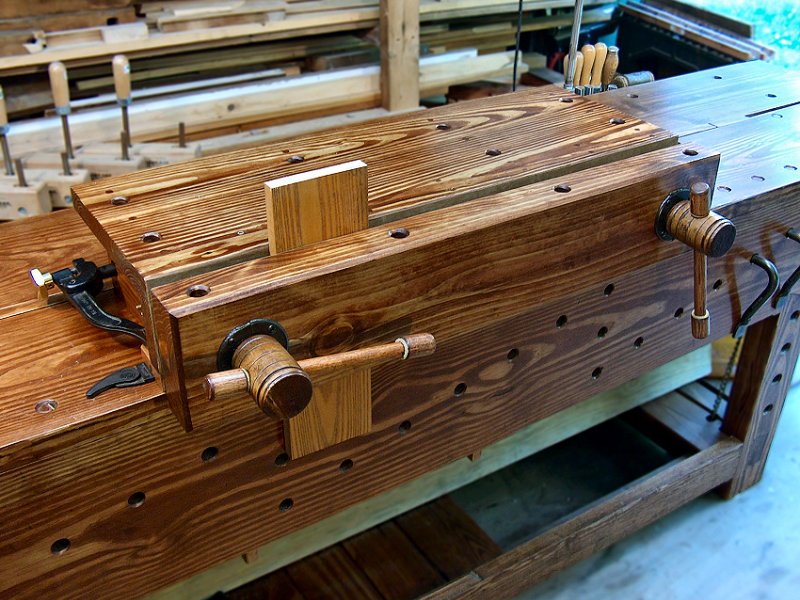
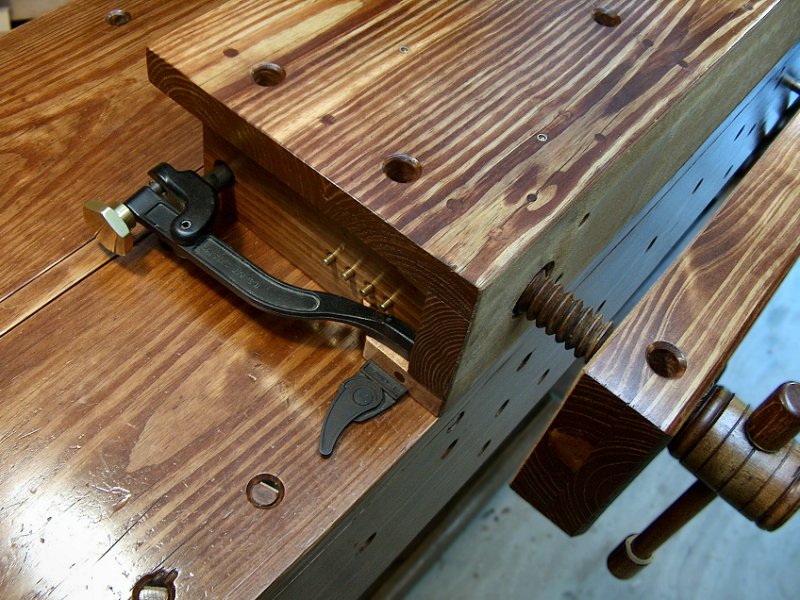
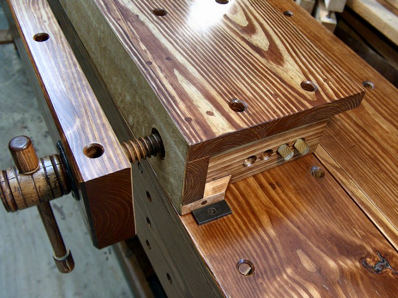
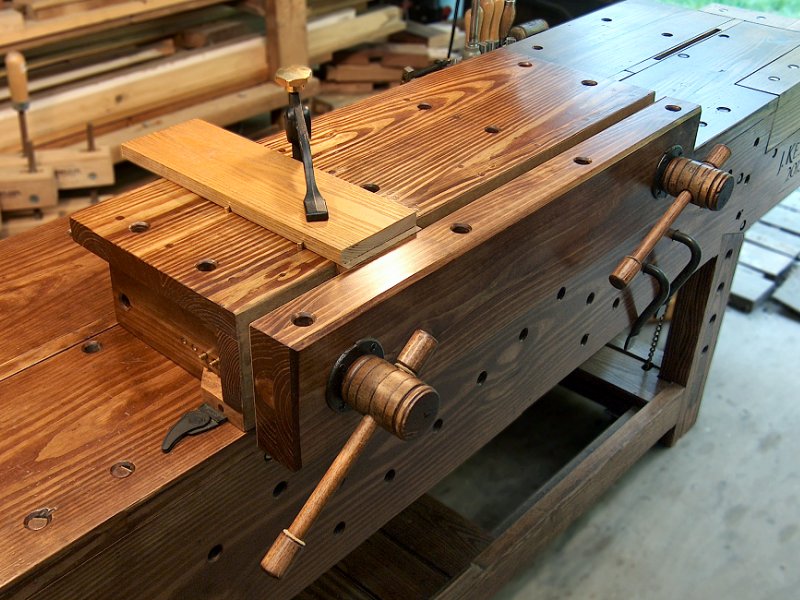
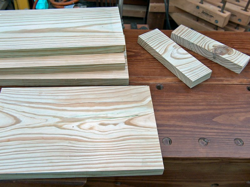
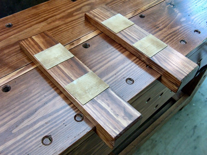
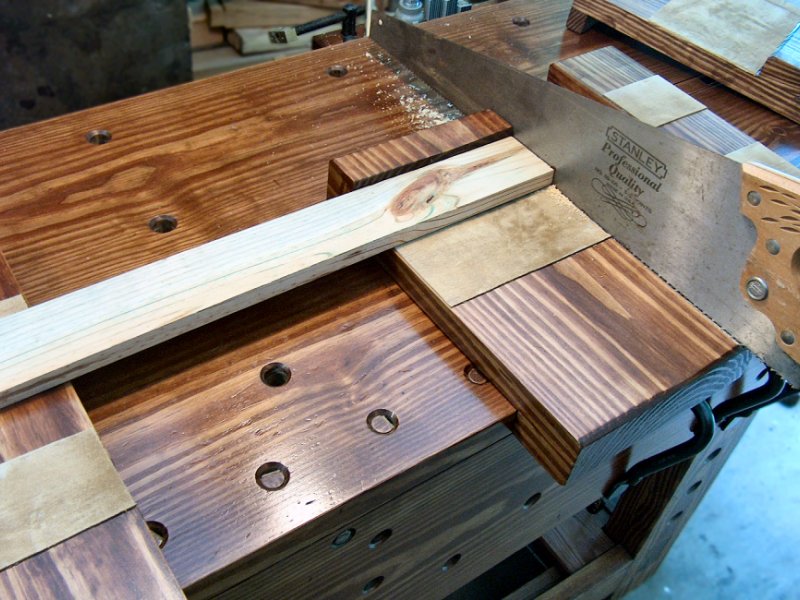
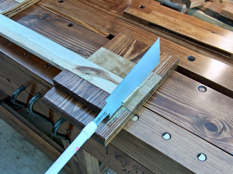
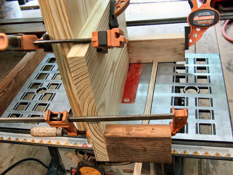
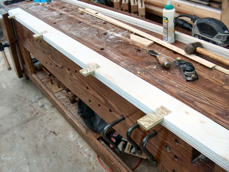
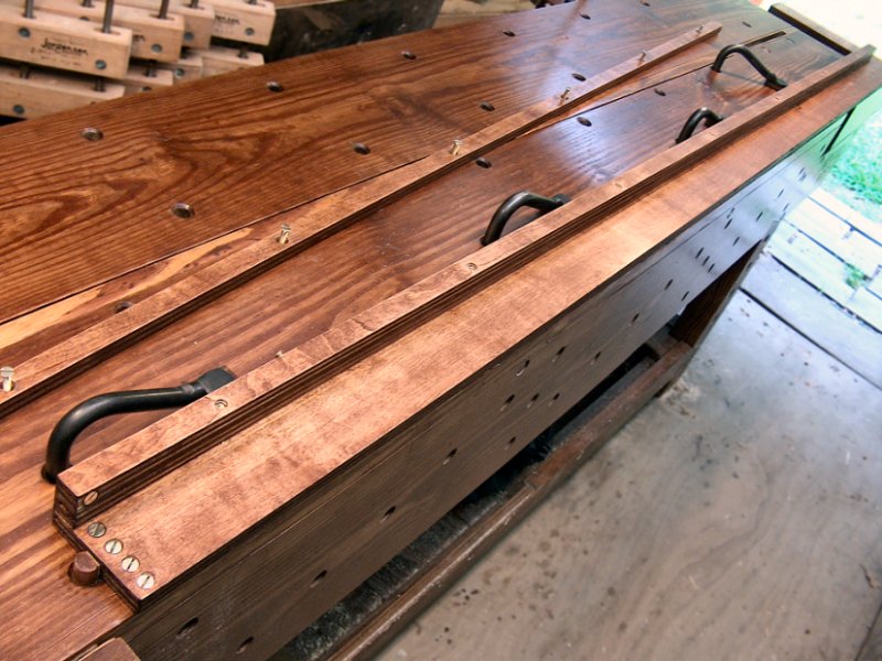
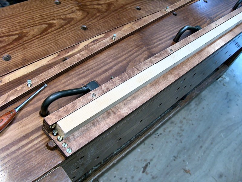
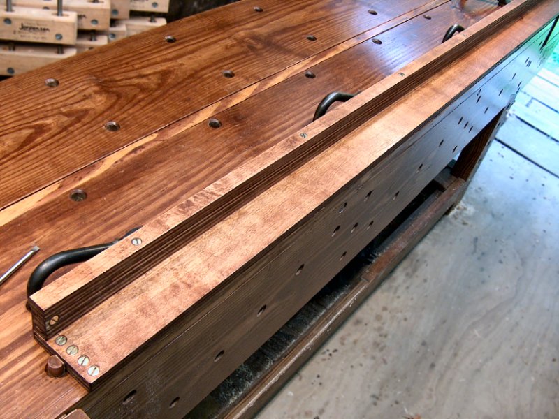
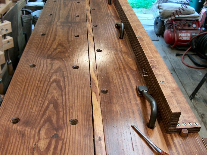
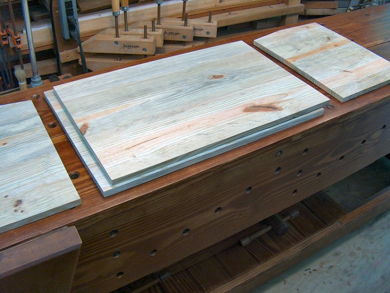
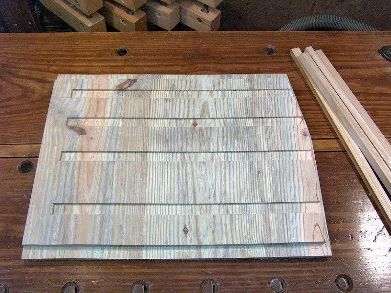
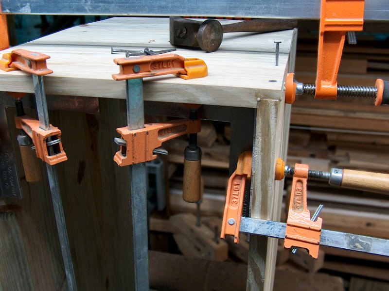
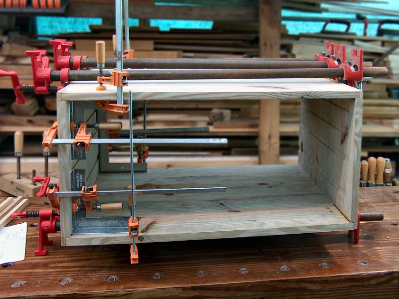