

Living Room Design
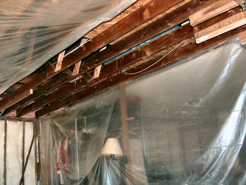
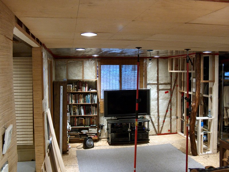
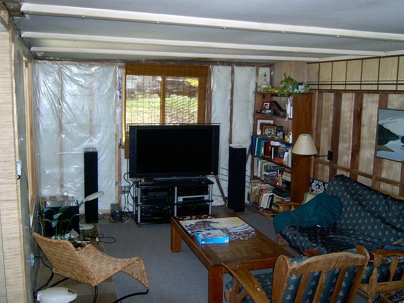 The current (2009) disappointing state of the living room (2 photos).
We spent a little time discussing plans for the living room early in the planning phase of our house renovation, however we really haven't done much to the space apart from incidental work resulting from other re-building projects (and it shows). The plan we settled on isn't anything spectacular, although the result should be a simple, open space that's functional and comfortable. With the removal of the funky old floor-to-ceiling windows in the Southeast corner and entry door from the Southwest corner, the South wall will be occupied by a built-in media center and shelving units. We also decided to completely remove the partition wall between the living room and bedroom, since it's not a bearing wall and really makes the house feel a bit chopped-up. That wall will be replaced with four fusuma doors, and allow us to open the entire interior of the house. In order to create an area to store the sliding doors when they're open, we'll build a sort of "pocket door" wall section in the Southeast corner, which will also serve as the back wall of a tokonoma display alcove for the living room.
 The basic plan for the new living room.
The Homasote® ceiling will be removed and replaced with a framed wood panel ceiling. The existing ceiling joists are quite out-of-level, dropping nearly 6-inches along their length from North to South. As was done in the kitchen, we'll add furring strips to the joists to create a level ceiling plane for the new wood panels, with a finished ceiling height of about 7-feet. Ideally we'd install a ceiling of wide Cedar planks to re-create a proper Sukiya style room, however the cost of the Cedar we'd need to do that is pretty steep. We'll try the wood panels first too see how that looks (I'm thinking light-stained 1/4-inch Birch plywood with a dark Spruce trim). If we decide to change it at a later date, it shouldn't be a huge project if the ceiling's already level.
The existing linoleum tile floor will be removed, along with the of 3/4-inch plywood underlayment. We'll lay down a new layer of 7/16-inch OSB underlayment, then finish the floor with "click-lock" laminate wood flooring. We've kicked around the idea of installing a kotatsu in the center of the room, which is a small table that has the floor cut out underneath it so you have a place to put your legs when seated at the table. I really like the idea of building one, since we don't have a dining room and it would provide a decent place to have a meal. In order to get a kotatsu built into the space, I'd need to form and pour a concrete box under the house to support the floor joists and provide a waterproof shell under the table. I'd also need to splice into the existing radiant heat tubing in the floor so I could heat the box area — that would be a pretty serious undertaking, so it's not high on the list of priorities. We'll see…
Building the Living Room
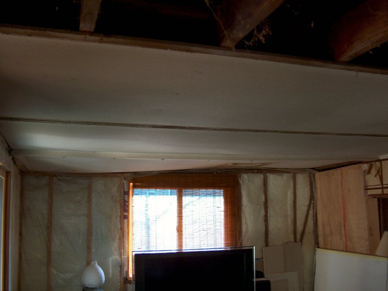 The ceiling goes away (1 photos).
Other than picking at parts of the room while working on other projects (installing the windows, stripping the paneling to use for the genkan ceiling, etc.), I doubt we'll spend much time working on the space this Summer (2009). I try to work on exterior projects when the weather is mild, and I'd like to finish the exterior paint and trim work this Summer. We'll likely go after the living room and bedroom soon, since we're both tired of living in the mess of a room that exists today.
Removing the Old Homasote® Ceiling: Winter 2017
In late 2017 I was contacted by a friend that's also working on a total home renovation to say he was getting a dumpster soon, and asked
if I had anything from our project that we needed to get rid of. This sounded like a perfect way to make the old, sagging
Homasote® ceiling from the living room go away. In exchange for a few loads of trash for his dumpster,
he also asked if I could help him remove his upstairs ceiling he was planning to re-build. Sure thing!
I got to work removing the Homasote® from the living room and the little hallway outside the bathroom, as well as some bits of paneling that were still on a couple of the interior walls. We ended up with about two truckloads of stuff for his dumpster, then got started on his place. His ceiling was all 2-foot wide pieces of 1/4-inch Oak plywood in 2-foot, 4-foot, and 6-foot lengths. It was in pretty good shape, and held up by little screws with trim rings every 16-inches or so. It took a while to get it all removed (there was no construction adhesive used in the installation, thankfully), but it will make a perfect "underlayment" layer for the 1/4-inch Birch finish ceiling I intend to install so it was worth the effort. I figure if I staple the Oak plywood to the ceiling joists, I can then glue and screw the Birch finish plywood to that to ensure there are no sags. That will also provide a full 1/2-inch of ceiling material, so the recessed light can "lips" will sit properly in the ceiling. We got all the Oak back to our place, then I started cleaning up the mess from the ceiling removal. After lots of vacuuming up of cobwebs in the ceiling joists, I stapled up some plastic sheeting to the ceiling joists to act as a temporary vapor barrier and called it good.
Replacing the Old Underlayment: Winter 2021 - Spring 2022
As detailed on the recently updated Bedroom page, we had an opportunity to use the same friend's dumpster
after Christmas 2021 to get rid of all the old linoleum tile and underlayment from the living room and bedroom. Since we had to re-arrange all the
furniture to get at the old underlayment, we also started installing new 7/16-inch OSB underlayment as we worked. To install the new underlayment
I was planning to use the pneumatic medium crown stapler with 7/16 x 1-inch staples and lots of subfloor adhesive. We hadn't gotten too far
along getting the bedroom OSB down, when a couple problems showed up…
I think it was the third sheet of OSB I was stapling down when the stapler just stopped working. I had purchased the Porter-Cable® MS200 stapler back in 2017, as I noticed after Black & Decker® purchased Porter-Cable® they had discontinued many of their pneumatic tools, and the rest we're lookin' to be not-so-great quality. I wanted to get the old metal-bodied style stapler to match the rest of my fine old Porter-Cable® pneumatics so I picked that thing up before they disappeared, but had not yet used it. Now I finally had a chance to put the stapler to work, and after a couple sheets it just stopped driving staples. I popped the air hose off the gun to investigate, and it turned out there was no air pressure — something had happened to the compressor. I parked the compressor out in the genkan while using it to help keep the noise down, so I went out there to see what was happening. I could smell some toasted electrics as soon as I got out there, and sure enough, the motor seemed to have had enough. The old "Job Boss™" oil-filled compressor was done. I looked online to see if I could find a proper replacement, and it seems no one makes portable, oil-filled, piston compressors any more (they're much quieter than oilless, diaphragm compressors, which is why I got that style in the first place). I checked the new Porter-Cable® portable units available at Home Depot, since I didn't want to delay the project while waiting for something to get delivered. They had a few little diaphragm units for cheap, but they seemed rather inadequate after having lived with the 3-1/2HP, 4-1/2 gallon beastie for years. I needed something now, so I found myself perusing Harbor Freight's site, and found what looked to be a decent replacement. They have a "Fortress™" series 5-gallon unit that looks identical to the old Porter-Cable®, but it has the same oil-free, diaphragm pump as all the rest. It also was a bit pricey just to get a slightly bigger tank and a couple tires. I ended up getting their 1-1/2HP, 4-gallon "Fortress™" unit for $250, and picked it up that afternoon. It's advertised as "Ultra Quiet", and much to my surprise, it really is much quieter than other oil-free, diaphragm pumps (and even quieter than the old Job Boss™).
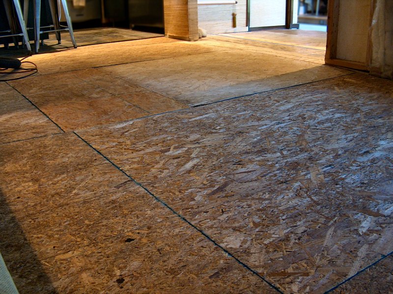 The new underlayment in the living room (1 photo).
The other trouble I was having while putting down the new OSB underlayment was dealing with cheap-o caulk guns. Neither the original underlayment,
nor the old subfloor boards had been glued down when the place was built. That made getting the old underlayment up very easy, but it also
meant the old floor was squeaking and creaking a lot. I figured if I shot a good amount of subfloor adhesive in the gaps between the old subfloor
boards where ever they lined up over a floor joist, the adhesive would be forced in and around the old boards when the OSB was stapled over it.
That meant I was using at least a full 10 oz. tube of adhesive (or half a big 28 oz. tube) per sheet, and getting that applied with a
basic caulk gun was gettin' old. The installation project was slightly delayed as I was waiting for a couple new cases of floor adhesive
to arrive after we'd finished the bedroom, so I started researching caulk guns thinking there must be a better way. Initially I looked into a
Milwaukee® M12™ cordless gun, since I already had plenty of batteries to run it. The problem is it's pretty much
only useful if you're applying caulk all day every day (like a siding or replacement window contractor might), and it's only available
for 10 oz. tubes, not the big 28 oz. ones that I prefer (and it's $150). After a bit more research, I found what I think are the
best caulk guns on the planet, from
Tajima Tool Corp.![]() .
It turns out Tajima Tool (now part of TJM Design Corp.) is Japan's largest hand tool manufacturer, started in 1909 (so they're the
Stanley Tools of Japan, basically). I'd never heard of them, but everything I read about caulk guns put their guns near the top of the list.
I also checked out the SolidWork German designed guns (their 10 oz. and 28 oz. models don't match, which is unacceptable, and they're really
expensive), as well as the good old Red Devil® guns like Dad used to have. For not much more money than
the Red Devil® stuff, I decided to try the Tajima guns and see if it really mattered. I picked up their
Convoy® Super 18 models in both 10 oz. and 28 oz. capacity (yes, I spent $90 on caulk guns, but they match).
Holy cow! That may have been the best money I ever spent on tools! These are outstanding in every way. The 18:1 thrust ration means a
gentle squeeze is all it take to get the fairly viscous adhesive to flow, then whenever the handle is released the plunger automatically
retracts 2mm which actually stops the flow from the tip. I went through two cases of 10 oz. tubes of subfloor adhesive and another half a
dozen 28 oz. tubes of construction adhesive on this job, and it was a pleasure to use these guns for application of all that material.
Like I said, money well spent!
.
It turns out Tajima Tool (now part of TJM Design Corp.) is Japan's largest hand tool manufacturer, started in 1909 (so they're the
Stanley Tools of Japan, basically). I'd never heard of them, but everything I read about caulk guns put their guns near the top of the list.
I also checked out the SolidWork German designed guns (their 10 oz. and 28 oz. models don't match, which is unacceptable, and they're really
expensive), as well as the good old Red Devil® guns like Dad used to have. For not much more money than
the Red Devil® stuff, I decided to try the Tajima guns and see if it really mattered. I picked up their
Convoy® Super 18 models in both 10 oz. and 28 oz. capacity (yes, I spent $90 on caulk guns, but they match).
Holy cow! That may have been the best money I ever spent on tools! These are outstanding in every way. The 18:1 thrust ration means a
gentle squeeze is all it take to get the fairly viscous adhesive to flow, then whenever the handle is released the plunger automatically
retracts 2mm which actually stops the flow from the tip. I went through two cases of 10 oz. tubes of subfloor adhesive and another half a
dozen 28 oz. tubes of construction adhesive on this job, and it was a pleasure to use these guns for application of all that material.
Like I said, money well spent!
With the new compressor and caulk guns on hand, I got back to installing the 7/16-inch OSB throughout the bedroom and living room. The bedroom was simple enough, but as I mentioned on the bedroom page, the living room offered a bit of a challenge. The problem was that the old floor was way out of level, and there was also a significant difference in floor levels between the old back porch and the living room (where the fireplace was located, long ago). I had no intention of trying to make the floors level, as there is nearly a 3-inch drop from the kitchen side of the floor over to the front of the house. My goal was to just get the floor even, with no little steps or drop offs. I'd been thinking of how to do this for a while before I started the project — using small, screwed down wood spacers, then spreading thinset mortar over an area and screwing the OSB to the spacers while the mortar was wet, or ripping long "shims" of 2 x 4 to put over the old floor joists, then filling the space with sand to remove any voids. It all seemed like a huge mess. The main issue I had to consider was that for the radiant floor heat to function properly, there couldn't be any air space between the subfloor (where the radiant heat stuff was attached to the bottom) and the new underlayment. With all that Oak 1/4-inch plywood I had from my friend's renovation project, I figured out another way: I could use the Oak ply to fill the low spots, then belt-sand off the edges to create gently tapered edges to transition back to the subfloor boards. I glued down the Oak ply with construction adhesive and a few staples, then remove the staples the next day and hit it with the old No. 40 scrub plane before belt-sanding it smooth. This worked pretty well for the low spots around the main floor support beam, however the small "step" at the old fireplace base and the drop-off at the kitchen floor tile needed something more.
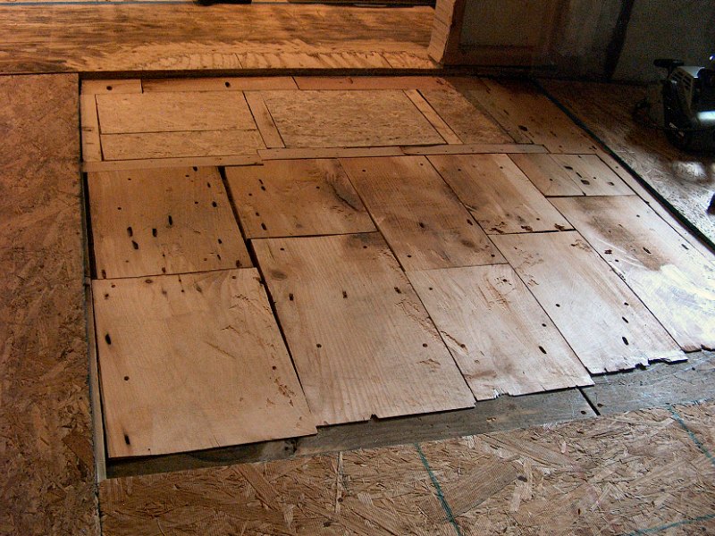 The "goofy shims" to even out the floor (3 photos).
When I installed the new kitchen tile floor I actually made that level, so that served as a guide for evening out the living room underlayment. With the old plywood underlayment and linoleum tile removed, there was about a 1-1/2-inch drop from the top of the tile to the subfloor near the fridge, tapering to a 1-inch drop near the bathroom. Most of the finish flooring we've considered for the rest of the house is just under a 1/2-inch thick (8mm + pad, or 12mm with pad attached), so I needed to get the new underlayment shimmed up to within a 1/2-inch or so of the tile. The old concrete fireplace mantle base was even worse, with nearly a 2-1/2-inch drop at the old porch floor. I needed something thicker than the 1/4-inch ply to fill these spaces (I had to save some for the ceiling, after all). Another project I've been kickin' around for years is to raise the attic floor a foot or so to provide more space for insulation. That means the existing attic floor of wide Pine boards will get removed, 2-by cross braces will be installed, then a new attic floor put on top of those. Since we had a truck available to bring a load of OSB to the house, I had also purchased an extra six sheets of OSB for the new attic floor. With the ceiling already removed, I had pulled all the nails from those attic floor boards, so we couild slide the OSB up between the ceiling joists into the attic (as there'd be no way to get 4 x 8 sheets up there if the ceiling was in place). That meant I had a bunch of 70-year old wide Pine boards in 10 and 12 foot lengths available from the attic. They all had a bunch of nail holes every 16-inches across each board, so it wasn't like I could do much with them. Those boards ended up as shim material for the living room floor.
To create the goofy floor shims I needed, I cut the boards into 4-foot or 6-foot lengths, then tapered them using the thickness planer. I'd start with the machine set to take about a 1/16-inch cut, then as a board started to feed and get planed, I'd crank up the depth setting (counting the turns) to take less material as the board continued to feed. When the board cleared the machine, I'd then crank the depth back down, add a couple turns, and repeat the process. This worked very well, and I was able to create 6-foot long "shims" less than a 1/4-inch think at one and, with the full 3/4 thickness at the other end. These long shims were then glued in place with a couple short screws to hold them while the adhesive cured over night. The next day the screws would be removed, and they'd get the same work as the plywood shims: rough them down as needed with the scrub plane, then smooth everything out with a 40-grit belt on the belt-sander. The work went fairly slowly (to allow time for each glued-down piece to cure over night, then figure out the thickness needed for the next piece the next day) but I made steady progress. After a couple weeks of this, all of the new underlayment was installed, glued down with plenty of subfloor adhesive, and stapled every 6-inches around the perimeter and every 8-inches or so across the sheet. My goofy floor shims actually worked, and the entire floor is very solid, with the high spots gently tapered into the rest of the floor, and no squeaks. Best of all, the floor was actually warm when the heat came on.
 Making the first ceiling joist level (4 photos).
Leveling the Ceiling: Winter 2022
Yes, it's been five years with a sheet of plastic for the living room ceiling. In the late Fall of 2022, with that miserable
bamboo containment work behind me, I finally got around to making some progress on doing something about a living
room ceiling. Part of the delay (aside from the bamboo work) has been trying to figure out a good method to make the ceiling actually level. I
didn't worry about making the floor level — I just wanted to get it even, as explained above. I felt the ceiling should be
level however, as the "plane" of the ceiling would be one of the first things you notice when entering the main house from the genkan.
The problem with the ceiling was that when the house was originally built, they spanned the entire distance from front to back with 26-foot long, straight-grained Douglas Fir 2 x 6 ceiling joists! Modern span tables don't recommend anything under a 2 x 10 for that span length, but apparently the price was right for the 2 x 6, so that's what they used (is it even possible to buy a 26-foot long straight-grained Douglas Fir 2 x 6 any more?). They did add some angled 1 x 4's between the ceiling joists and the rafters to help a bit, but that's still not much lumber up there. The odd bit is that the ceiling isn't lower in the center (because of sagging ceiling joists), but instead it's lower at each end of the joists. I don't know how they managed to make that happen, I mean, if the footings and foundation sunk after they were built (which is what it looks like happened), then why did the middle of the building not sink too? There were no supporting walls in the center of the house to keep the middle higher when the perimeter sank, but the 6-foot level doesn't lie — the joists are significantly higher in the middle of the house than at their ends. The only explanation could be that after they finished the roof sheathing, they jacked up the center of each joist a few inches as they nailed in those "sorta-truss" pieces between the roof rafters and ceiling joists.
Regardless of how it got into such a state, I wanted to make it level again. I've talked about various options with friends that are also doing renovation work, but didn't like the sound of their recommendations. Most said the easiest thing to do would be to add a new 2 x 6 to the side of the existing joist by leveling the new piece, and then glue & screw it to the old joist. Sure, that would be simple enough to do, but it would also add a lot of weight to the ceiling, and be fairly expensive to pull off. The living room ceiling area is roughly 12-feet by 18-feet with a joist every 16-inches, so that's a couple hundred bucks of new 2 x 6 stuff. Others suggested installing a drop ceiling, with composite tongue & groove ceiling boards that snap onto the drop ceiling metal grid. Again, a bit pricey and I'm not thrilled about the look. I'm leaning toward going with a finished ceiling of stained Birch plywood panels in 16-inch widths, and 2, 4, and 6-foot lengths. I finally decided to make more "goofy shims" that get glued & screwed to the bottoms of the existing joists to make them level. I've got a decent pile of old straight-grained Douglas Fir 2 x 4 studs from various walls that have been removed or rebuilt, so I'll see how much of that stock I can use up to make the ceiling level.
 Working across more of the ceiling (4 photos).
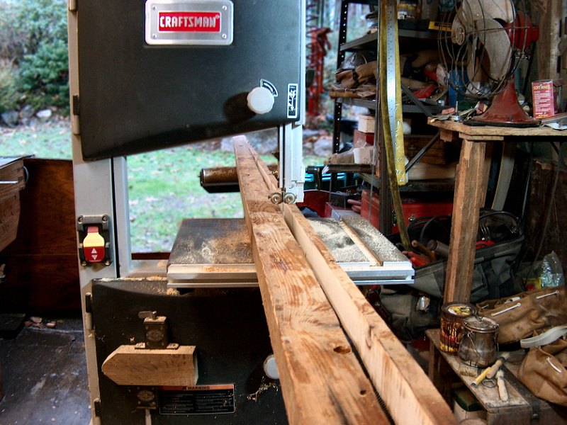
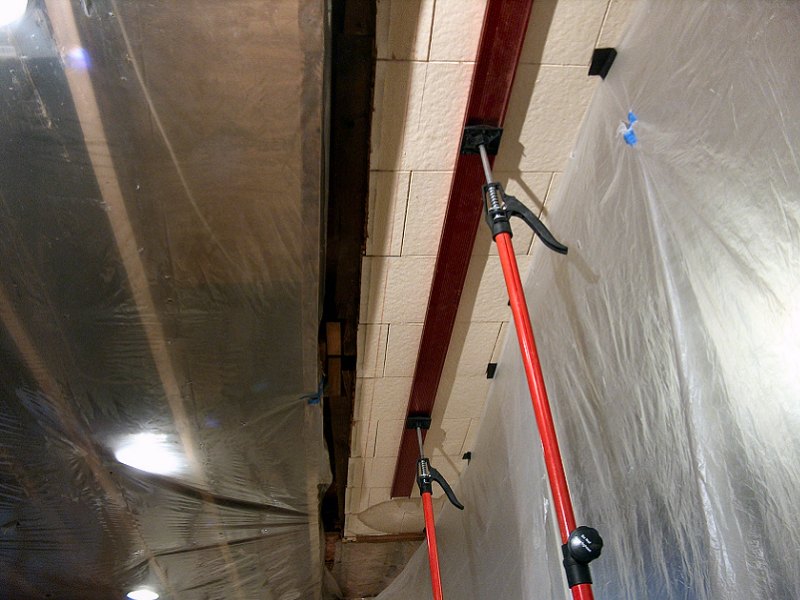
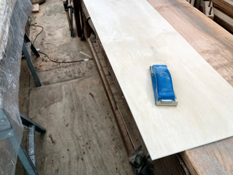
To get started, I needed to find the lowest spot in the room, which turned out to be the Southwest corner (the front, driveway side). The plan was to then clamp a 2 x 4 to the side of the joist and make the 2 x 4 level. Next, I'd trace the bottom of the joist line onto the 2 x 4, then cut to the line with the bandsaw and glue & screw the new "shim" to the bottom of the ceiling joist. That plan didn't last long. The first joist is an inch-and-a-half away from the wall (nailed into the gable end wall footer), so there's no way to get a clamp around the joist and 2 x 4. No problem... level the 2 x 4 and put a couple screws through it into the joist. Of course that only leaves an inch-and-a-half wide space to work in to scribe the line. Alrighty then... sharpen a pencil, then cut it off so it's an inch long. Success! Well, sort of... The drive belt on the bandsaw was old enough that it shredded the first time I turned it on (since I haven't really used the thing for a couple years). I ordered a new belt, then cleaned up the saw a bit and put on a fresh blade. With the new belt installed, I then sliced off my first shim piece. That 70-year old Douglas Fir sure cuts nicely. I then hit the thing with the Stanley No. 6 to take off any gross high spots, followed by a quick pass with the 60-grit belt sander to even everything out.
With the first shim installed, the plan was to then flip the cut-off piece around to use for the next shim section. Nope. The 2-1/2" wide piece wasn't wide enough at one end to sit level and still touch the ceiling joist. Most of these old studs are just over 7-feet long (the old ceiling was about 7-foot 6-inches high. Take away the double header and footer, and you get a 7-foot 1-1/2-inch long stud). The first shim went from nothing to about an inch thick, so the next one started at an inch, but was gonna need more than the remaining 2-1/2-inches at the other end — and I still had another 4-feet to go to make it to the kitchen ceiling. The idea was to cut the thin shim first (at the front of the house), then flip the leftover for the next shim. The ceiling was so outta whack that I couldn't get both shims from a single old stud. Ah ha! I could raise up the next shim a bit. When I installed the final ceiling it would still be level, with some little 3/8-inch offsets from one 4 x 8 area to the next. The trim would make that barely noticeable... yeah, that'll work (Nope, but we'll get to that in a sec). I made a little 3/8-inch thick block as a spacer, then was able to cut the next shim. The final four-foot length for the first joist was then marked with the same 3/8" off-set, and I had my first joist leveled from one end to the other.
With a level joist to work from, I then repeated the process on the next joist. Again, doing the same 3/8" off-set on the second shim. As I got the piece near the kitchen marked, it was looking like 3/8" might not be enough to have the 3-1/2" wide 2 x 4 do the job. It actually had enough material, but no way it was gonna work for the next joist. Time to revise the plan again... I gave it some thought and decided there was no reason to leave the off-set "step" for the finish ceiling. I could off-set the 2 x 4 however much I needed to have stock available for the shim cut, then just tack another piece of lumber to the bottom of the installed shim to keep all the joist bottoms at the same level. I milled some stock to 3/8" thick and glued that to the bottoms of the first two joists, then decided to just finish working along on each joist where it met the kitchen ceiling — this end of the room is where there was the biggest difference between the existing out-of-level joist bottoms and the new level joists along the side of the room, so getting a level end with three-foot long or four-foot long 2 x 4's all along the kitchen ceiling would give me a good idea of what I'd need to do for the rest of the room.
 The living room ceiling is level! (3 photos)
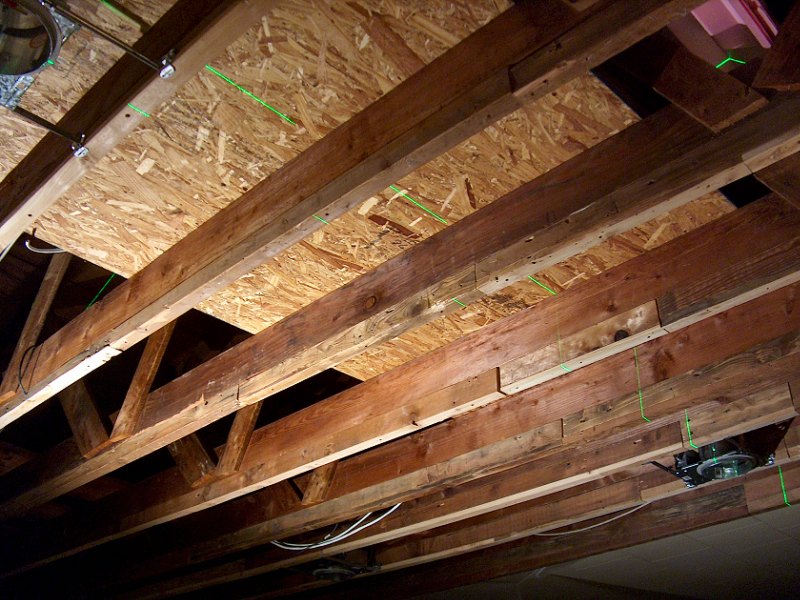
I worked my way along each of the 10 joists for the living room, and by the time I got to the last one near the bathroom door, I had to use a full 1-1/2" off-set to have enough material available to scribe a 2 x 4 for the shim (so yes, I'm adding an additional 5-inches of lumber to the bottom of my ceiling joists in that area of the ceiling). At least that's the biggest gap — everything from that corner and back across the rest of the ceiling will be smaller and smaller shims.
With the kitchen end of the ceiling set level with the joists along the entryway side, working across the rest of the room proceeded without difficulty. Every day I would get two or three joists taken care of, until I finally got the last one done the day before Christmas eve. That allowed us to get the tools put away and then get our Christmas decorations out on Christmas eve. Even though I had tried to keep everything level to the previous piece, I noticed a couple joists we're a little "off" here and there as I was putting the plastic vapor barrier back up. I had leveled from one joist to the next at the end near the front of the room when starting a new joist, then leveled each section of that joist to the next section until I reached the short bits near the kitchen. Sometimes there would be a little 3/16-inch step by the time I got to the kitchen piece, or it would be right on the money, but not perfectly level across a few joists. I doubt any of these little differences would be noticeable in the finish ceiling, but I still wanted to try and get everything as close as possible.
To finish the "ceiling joist leveling" project, I used the 6-foot level across four joists to see if any joists were low. If the level didn't "rock" from one joist to the next, I could move it along a couple feet, and check again. It seemed every joist was now level along the length, but there were a couple areas that "rocked", which meant something was low. Some of this was caused by a little twist in the joist — which meant the bottom of the shim had one edge lower than the other. A few light strokes with a block plane along one edge of the shim usually made things right, although there were a couple joists that were just too low along nearly their entire length. Taking an 1/8-inch or more of material off a 12-foot section of joist above my head was not gonna happen with a hand plane (I tried on one piece... Nope). A quick run to Harbor Freight tools and $50 later, I had a little power planer which preformed quite well at getting all the joists as close to level with each other as possible. That'll do.
Ceiling Lights Installation: Winter 2022 - 2023
With level ceiling joists to work from, we could now make some real progress on the living room. The next thing to address was the wiring for the various lighting
fixtures, as well as the ceiling mount speaker locations and the fresh air duct for the heat recovery ventilator. That also meant I needed to head back to town hall
and figure out how to get my building permit back in order. When a building permit is issued, if no progress is made for two years (which generally means some
manner of inspection occurs for completed work outlined in the permit), the permit expires. I had gotten a building permit for all the interior renovation work
long ago (which was mainly for electrical work, and re-locating the bearing wall between the bedroom and laundry room / closet), but the last thing that was
"officially completed" on that permit was the living room wall plug wiring inspection, in 2009. I could proceed with light fixture installation and wiring,
but I'd need a fresh permit (or try to get my old one "renewed") so the wiring can be inspected before putting in the finished ceiling and insulation
in the attic.
 Back to the drawing board (3 sheets).
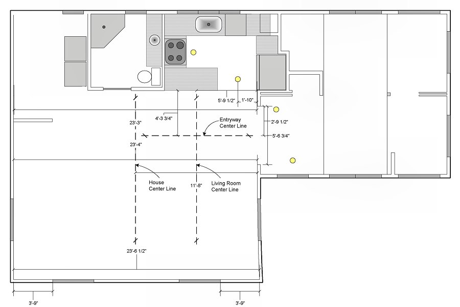
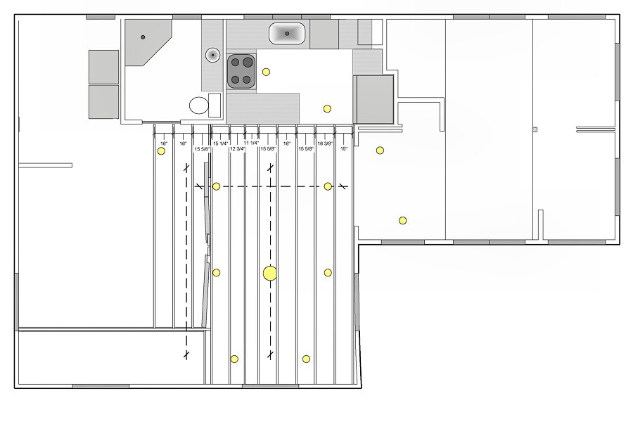
My original household re-wiring plans (see the Wiring Plans section of the Wiring page, with all plans available in the Mechanical Systems Data section of the Specifications page) had laid out eight, 6-inch recessed light "cans" for the living room perimeter, along with some manner of semi-flush or flush mount fixture in the center of the room. Now that it was time to actually get these things installed, it was obvious that there was no need for eight cans. We fiddled around with a couple of portable clamp work lights to get a better idea of where the lights should go, and decided six cans would do the job nicely. To work out the precise placement, it was back to the drawing board, literally, to figure out the correct positions for everything.
After looking over some of my old floor plan files and comparing their measurements with actual measurements in the room, it was clear a few things didn't quite match between the drawing and reality. Apparently when I did the foundation repair and rebuilt the Southeast corner walls of the living room, I didn't get things lined up very well and that East wall is a bit out of whack (the vertical wall near the center of the plans at left). I tweaked the plan to show reality, and it was clear that measuring from the East wall to the center of the ceiling wouldn't work. Based on the measurements of the space, it looked like the best way to proceed would be by starting with a couple centerlines, then measuring light positions off the centerlines. The kitchen ceiling/floor line is perpendicular to the entryway wall (at least until it gets to the part I rebuilt back in 2006), and parallel to the South wall — that line would work as the starting point to get things laid out.
With light positions worked out on paper, the next step was to actually get them in to place. That meant making accurate measurements from centerlines that only
existed on paper, and there was no ceiling in place upon which to make marks. Time to finally get a laser level. Of course, my first stop to find a nice laser level
was to check for a Milwaukee® M12™ unit. Sure enough, they have one, but it's $400 for the bare tool. Ouch. After lots of online
research and browsing tool retailer's web sites, I ended up ordering a HiLDA®
Laser Level ![]() from Amazon for less than 80 bucks. There were
lots of recommendations out there for stuff from Huepar®, but it's two or three times the cost of the one I got, and I don't anticipate
getting a ton of use out of the thing so I went for the cheapo (and I'm not gonna buy a tool that's lime green… or yellow, or blue. Yeah, I've got issues).
from Amazon for less than 80 bucks. There were
lots of recommendations out there for stuff from Huepar®, but it's two or three times the cost of the one I got, and I don't anticipate
getting a ton of use out of the thing so I went for the cheapo (and I'm not gonna buy a tool that's lime green… or yellow, or blue. Yeah, I've got issues).
 Installing the lights (2 photos).
Wow, that laser level sure made things simple! I was very pleased with how well it worked, and I can now see putting this thing to good use for lots of upcoming projects. Anyway, we started by shooting a line onto the edge of the kitchen ceiling with a perpendicular line centered in the living room (measured over from the entryway wall). That centerline got marked on the header on the South wall and the ceiling framing at the kitchen, then we moved the laser to put the perpendicular line in the center of the entryway. Now it was a simple matter of holding the tip of the tape measure on the centerline, then measuring over to the position of the first light centered on the entryway line. The rest of the lights went up very quickly, with a minor tweak to the position of the lights over the future fusuma doors due to a ceiling joist being in the way (it's only a difference of a couple inches, which is barely noticeable). For the center light, we just rigged up a simple clamp-on worklight in the attic and moved the position a few times until we liked how it looked.
With all the lights in their correct positions, I then got busy connecting everything to the switches and wiring I installed back in 2009 and 2010. The recessed lights were connected to the Lutron® Caséta® PD-6WCL dimmer and Pico remote dimmer (with nightlight) I installed last year for the 6-inch recessed lights in the kitchen and entryway. The new center light 3-way switches were then swapped out for another Lutron® Caséta® dimmer switch and remote that are the same as the recessed light controls. On to the rest of the ceiling work… which is easier said than done.
"We can't because…" Winter 2023
That has been the answer to almost every project the home owner has asked about over the last 20 years of this seemingly never ending renovation project.
Doing the demolition work to the original space happens very quickly, but putting it all back together just drags on for years. The rebuild work has to happen
in a certain order, or it'll need to keep getting re-done to take care of things that were skipped. It started with stripping the walls back to studs. Okay, let's
put up the new gypsum wall board (GWB). We can't because we need to get the wiring installed. So do that? We can't because we need the new electrical panel put in.
Okay, panel and wiring done. Great! Let's put up the GWB. We can't because we need to remove the floor and put in new underlayment. Done. GWB? We can't because
we need to remove the old ceiling. Done! GWB? We can't because we need to level the joists and install the ceiling panels. Okay, joists leveled. Ceiling panels? We can't
because we need to install and wire the ceiling fixtures. Done. Ceiling panels? We can't because we need to add framing for the ceiling panels. So do that? We can't because
we need to remove some of the bedroom ceiling. Okay, do that then install the ceiling panels? We can't because we need to build a header for the sliding doors.
Great, do that then? We can't because we need to remove and rebuild the attic floor. Ah, so that's next? We can't because we need to install the rest of the
Heat Recovery Ventilator (HRV) duct work. I see… so duct work, then ceiling panel framing, then attic floor, then ceiling panels, then GWB? Close, but we
can't because we need to build the walls for the tokonoma… This is why we've had living room walls of plastic covered insulation for 12
years, and a living room ceiling of a plastic sheet with no insulation for five years. I'm as tired of looking at this pathetic mess as she is.
 More plans to make progress (6 sheets).
The good news is that all those little "We can't because…" project blockers are finally getting addressed as we move forward with the work. The items we can deal with in fairly rapid order are the header for the fusuma doors, then the HRV ductwork, followed by the framing to support the finished ceiling, and then the framing and wiring for the tokonoma. Naturally, this all starts with another set of fresh plans to figure out exactly where those doors and walls are supposed to go. While working on the plans I ordered all the HRV ductwork (thank you Home Depot for free delivery), and even managed to have a friend take me on a lumberyard run for a load of 30 2x4s for the attic floor, tokonoma framing, and door header. Progress!
I prefer to get things worked out on (digital) paper before I start cutting, as it helps me keep the proper "build order" in mind. The series of
plans at the left start where the lighting plans left off, with the correct measurements for what parts of the room are straight and where the perpendicular centerlines
are located. That gives me the correct position for the HRV fresh air inlet, the layout for all the "ceiling underlayment" (the 1/4" Oak plywood),
the ceiling mounted Dolby Atmos® surround speakers, the finished ceiling (1/4" Birch plywood), and any additional framing
the finished ceiling requires for nailers. Have a look at the plans for more information (also available as Ceiling
Plans ![]() ), then head over to the HVAC
page in the Mechanical section if you're interested in the details of the HRV ductwork installation. Once that ductwork for the living room fresh air supply is in place, I can
get back to more of the living room ceiling carpentry work.
), then head over to the HVAC
page in the Mechanical section if you're interested in the details of the HRV ductwork installation. Once that ductwork for the living room fresh air supply is in place, I can
get back to more of the living room ceiling carpentry work.
The Fusuma Doors Header & Other Ceiling Framing: Winter 2023
With the ductwork in the attic I wanted to get in place while the ceiling was open taken care of, the next thing to deal with was the header for the
fusuma doors that separate the living room from the bedroom. The original wall between the living room and bedroom wasn't actually in the center
of the house (the bedroom was wider than the living room by a few inches), so I needed to get the correct centerline measured and marked, then cut away a bit
of the bedroom ceiling so I'd have room to work on that header. Some careful measuring at the kitchen end of the living room let me get a perpendicular centerline established
with the laser lever, then I marked the cut line and sawed off a few inches of the bedroom ceiling tiles and strapping with the 5-1/2" Skilsaw™.
 Putting up the door header (6 photos).
To hold up the new header I added a couple of Simpson Strong-Tie® HUC Face-mount Concealed-flange 4x4 hangers at the bathroom wall top plate and the front wall top plate to hold up each end of the thing, then set about figuring out how to install an 18-foot, 1-inch long header into that space with pretty much no room to work. The only thing I could come up with was to build the header in two sections, then join them together with both pieces in their final position. Before I put the header in place, I also needed to get the nail blocks for the finished ceiling into that first joist bay next to where the header was going, so I would have room to get the nail gun in there and attach those blocks (again, getting all this figured out on the plans first ensures things go together in the right order). I ripped some 2x4 chunks in half on the bandsaw for the nail blocks and got those nailed into place, then built the header. The header was made of a 10-foot 2x4 and an 8-foot, 1-inch 2x4 glued and nailed together with a 1/2-inch thick piece of plywood in between. The front piece went in first, held in place with a FastCap® 3rd Hand, then the chunk at the bathroom wall went into position (with the 1/2" ply core spanning the joint) and the whole works was nailed together with the big framing nailer and 3-1/2-inch long nails every couple inches. To help support the header along its length, I then added some small blocks of 2x4 between the header and the nearest ceiling joist every 3-feet or so. These were tacked to the joist and glued in place, then a 6-inch long FastenMaster® TimberLOK screw was driven through the joist and block, then into the side of the header. I also added a cross support of 2x6 above the center of the header, nailed through a ceiling joist on each end, then ran another pair of TimberLOKs up through the header and into the 2x6. Ceiling framing was mostly done with the rest of those finished ceiling nailer blocks installed as needed according to the plans. I'll need to add some more material above the tokonoma framing once that's worked out, and that will make it ready for the first layer of plywood.
 The plan for the tokonoma (1 sheet).
Building the Tokonoma: Late Winter 2023
When we started this entire renovation project over 20 years ago, one of the goals was to emulate the sukiya style home design, with fairly simple wood
and plaster interior surfaces and trim, along with certain key Japanese architectural components typical of the late Edo period. These elements include the
engawa influenced back deck, the genkan of the main entry, and the fusuma doors and
tokonoma alcove in the main room. With the header for the fusuma doors in place and the ceiling rough carpentry completed,
it was time to work out the details of the tokonoma at long last. The troubling issue with getting a "formal" tokonoma
into our space was that the tokonoma is actually part of a larger design component called a hondoko, and there simply wasn't
enough room to make it happen. To have the fusuma doors "make sense", they would run from the bathroom wall toward the front wall, and
fill 12-feet of that 18-foot long open space (with each door being 3-feet wide). That left us a 6-foot long section which would neatly hide the two sets
of doors when they were all in the open position, which is where the problem comes in...
As mentioned above, a formal tokonoma is one part of a hondoko, which also has a shelving alcove (the tokowaki) to the right of the display alcove (the actual tokonoma, or just toko), and then a low desk with a window (the shoin) to the left and perpendicular to the display alcove. The shelf alcove is supposed to be the same width as the display alcove, which would mean we only have room for 6-feet of sliding doors — and that would put the couch in front of the alcoves, which would make no sense and look fairly silly. There are also "rules" about how high the cross bar for the tokonoma front wall is supposed to be (the otoshigake) relative to the height of the door header (the nagaoshi), and how high that's supposed to be relative to the ceiling plane, along with strict dimensions for the spacing of shelves in the tokowaki, and the height of the floor of the tokonoma relative to the room floor. We're not going to worry too much about most of those "rules" (and we can't do anything to raise the entire room height to meet those various relative height offsets anyway), so we just decided to try and make it work within the available space. This also works fine within the sukiya style concept, which is much less formal than the more strict shoin building style. The biggest difference between our tokonoma and a formal hondoko is that I re-located the entire shelf alcove to the usual position of the shoin (perpendicular to the left side of the toko), and there's no shoin at all (although the media cabinet and window above it will kinda-sorta look right). The other big difference is that both the display alcove and the shelf alcove aren't actually alcoves, but instead stick in to the main room – with the shelves sticking into the toko. I won't tell if you don't.
 Framing the tokonoma (4 photos).
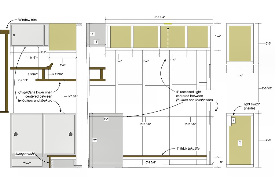
With the basics of the layout decided upon, the next step was the usual time spent fiddlin' with a plan to work out the actual dimensions of the thing (see above). Based on the walls I knew were plumb and square, the first measurement was to ensure the thing would be deep enough to house the fusuma doors. After adding the depth of the little bump stops, trim, and a wall covering, that worked out to be 6-feet, 1-3/4-inches. Of course the front wall isn't plumb, and the floor isn't level, but I got it worked out to ensure the toko would be long enough and got busy framing the thing. Some of the dimensions were also determined by what was going to happen in the shelf area, which contains a set of offset shelves in the center (the chigaidana), then an upper shelf/cabinet with sliding doors (the tenbukuro), and a larger bottom cabinet with sliding doors (the jibukuro). The typical dimensions of "western" console furniture are basically 32-inches tall and 22-inches deep, so I used that as the size for the lower cabinet (as well as the height of the lower wall section at the right end of the toko). The upper shelves/cabinet were then set to half that depth, so 11-inches deep. To reduce some of the "bulk" of the walls, I also used 2x3s for the framing of the upper walls instead of 2x4s. After adding a fair amount of additional ceiling framing to provide something to attach the finished ceiling to, the last step was to get the 4-inch recessed can installed. Rather than center that light in the entire width of the toko, we instead centered it between the front of the lower cabinet at the left, and the end wall on the right. This will put the light nicely centered when we hang a scroll in the finished tokonoma. I also kinda hid the light switch on the inside of the right side wall, instead of putting it up in the middle of the back wall. We're quite pleased with how it's lookin' so far.
Installing the Ceiling "Underlayment": Late Winter/Early Spring 2023
After the tokonoma framing and wiring was completed, the living room was ready for a new vapor barrier followed by the installation of
the first layer of the finished ceiling, which I'm calling ceiling "underlayment" for lack of a better term. The idea is to get to a 1/2-inch thick
finished ceiling (since that's what recessed lights and electrical boxes are designed for), so we'll use 1/4-inch Oak ply as the first layer, then
the finish layer will be 1/4-inch stained Birch ply. But first the new vapor barrier went up — which started with a fresh roll of 6-mil plastic, pulled
tight then stapled every foot or so to all the ceiling joists. All the staple penetrations were then carefully sealed with tape, and the entire perimeter
also got taped to the wall vapor barrier at the edge of the ceiling. An undersized opening for each light was then cut in the plastic, the plastic pushed around
the edge of the can, then hit with a healthy layer of clear caulk. The living room ceiling was air sealed at last.
The 1/4-inch Oak ply then went up without much trouble. I started at the kitchen end of the room, aligning the ply to the edge of the ceiling at that end, then just started bangin' away every 8-inches or so with the medium crown stapler. I did have to adjust the stapler a bit and turn down the output pressure of the compressor, since the first couple staples just blew right through the plywood. Once things were adjusted properly the work progressed without issue, alternating the seams of the 8-foot long pieces and 4-foot long pieces as I worked across the ceiling. For the edges of each piece near the walls, I had to switch to the narrow crown stapler (with 7/8" staples) as the body of the medium crown gun was too big to fire a staple flush into the edge. The openings for the recessed lights were carefully measured then made with a 6-3/8" hole saw I'd purchased years ago for the recessed lights in the genkan, kitchen, and bathroom. I managed to get the entire ceiling done with the available plywood, although the last bit at the front of the house had to be filled in with some little 8-inch wide pieces — most of the ply I had been given was actually 23-inches wide and not a full 24-inches, so that difference added up as I worked across the room, which resulted in the 8-inch gap I filled in with cut-offs.
 The ceiling "underlayment" installation (3 photos).
We also noticed there were a few spots where the Oak ply was a bit bowed, which resulted in a small "step" from one piece to the next (you may notice some of these little "steps" in the first photo at the left). To ensure the finish ceiling didn't transmit these offsets, the lovely bride went into the attic with a handful of little chunks of 2x4 and a 6x6 block. I tapped on the ceiling from below so she could find the bow spot, then she'd span the seam with a chunk of 2x4 and hold it in place with the 6x6 to remove the bow, and I'd secure the 2x4 from below with the narrow crown stapler. It worked very well, and the whole ceiling appeared very smooth and even when we finished.
The only remaining task for the "underlayment" installation project was to get the ceiling mounted Dolby Atmos® speaker openings cut. The two pieces of plywood where the speakers were going to mount had been temporarily installed with a few screws rather than staples, so I could remove those pieces to the shop and cut the speaker openings. The problem was that the speakers I had initially selected late last year (a pair of Monoprice™ "Alpha" 6-1/2" Carbon Fiber 2-way speakers with 15° angled drivers) were on seemingly endless backorder. The were originally supposed to be in stock at the beginning of February, but every time I checked the site, the ETA kept changing to a few days later. I was not going to attempt to cut the speaker openings until I had the speakers in hand as I wanted to be certain the hole size was correct, since the speaker is held in place with little screwed "flaps" at the edge of the opening. They finally became available on the last day of February, so I immediately ordered a pair. The 6-1/2 inch speakers require an 8-3/4 inch opening, so now that I had the speakers I could determine exactly where to make the openings.
It turned out that the original planned location for the speakers just wasn't going to work — the 8-3/4 inch speaker diameter at that location put the speaker right next to where the attic truss boards are attached to the ceiling joist, and that joist bay on the bedroom side of the living room only has 9-inches of space available. With the 3/4-inch thick truss boards in there, there's just not enough room for the speaker. My first thought was to move the speakers a little closer to the kitchen (so they'd be centered in the finish ceiling panel there, rather than flush to one edge), but there wasn't enough speaker wire available to comfortably make that connection. They were going to need to move closer to the front of the living room, which meant the openings would end up in a piece of plywood that was already stapled in place. So be it. I removed the screws from the original location sheets and got those properly secured with the stapler, then fiddled around with measurements to find a new location for the speakers. I decided to move them to align on what will eventually be a seam of the finished ceiling panels, a little closer to the front-to-back center of the living room ceiling. I marked and cut the openings with the jig saw working overhead (which wasn't as bad as I'd thought), cleaned up the openings a bit with a rasp and sandpaper, then caulked the vapor barrier to the ply around the perimeter of the hole. Because the speakers can't actually be installed until the finished ceiling is up (the flange of the speaker presses against the finish ceiling, with the "flaps" screwed down for pressure against the underlayment), the last task was to add a couple TENMAT® recessed light covers in the attic to seal the speaker openings. These mineral wool "buckets" were trimmed and fit over the speaker openings, the speaker wire fed through the edge, then held in place with a liberal application of spray foam. The living room is now ready for gypsum wall board and finished ceiling installation (which will happen after I finish the work in the attic and then get the bedroom walls and ceiling taken care of as well).
Finished Ceiling Panel Prep Work: Summer 2024
With the rest of 2023 spent working on the attic, most of Spring and Early Summer 2024 was spent working on the walk-in closet/laundry room
and the bedroom to get all the walls finished in those rooms before moving back to living room work. By late June the closet was mostly done and work
was underway in the bedroom, but then I got a chance to go pick up all the plywood and run it through the table saw at my friend's shop for the
bedroom and living room ceilings. After a full day of work at his shop, I ended up with a sizeable stack of 1/4" SandePly plywood, cut to
16-inch wide strips of various lengths (each of the 13, 4 x 8 sheets was cut into one 8-foot strip, one 5-foot and 3-foot strip, and one
6-foot and 2-foot strip). I had originally planned to use Birch plywood for the ceiling, but the cost of plywood sky rocketed during the
pandemic a couple years ago, and never came back down. 1/4" Birch that used to run less than $20 a sheet is now nearly $50 per sheet,
and the SandePly stuff is less than $30 per sheet, so that's what I ended up purchasing. After lots of sorting through their stack, we ended
up with very clean stuff with no knots or filler on the "face", and fairly interesting grain. Apparently this stuff is a hardwood
plywood, faced with Gmelina (a.k.a. Beechwood or Ghamar - none of which I've ever heard of), and I think it will
do the job nicely.
Before installing any of this material, I first wanted to get all the finish application done on it (since I can't imagine the mess of trying to apply stain and topcoat to the ceiling). The problem was that I didn't really have anywhere to do this work all at once inside the house. All the stock was stacked in the genkan, so I just applied stain on a couple pieces on the stack each morning. By late afternoon those two pieces were dry enough to get stacked on edge in the bedroom, and then I could do two more pieces on the stack and let them dry over night. Once I'd gotten color on all the 8-footers, I then decided to give them all another coat of a different color stain to highlight the grain a bit more. The Olympic® semi-transparent "deck" stain provides an even color to the wood, but even while wiping it down after applying it doesn't show much grain detail. I decided that once the stain had dried over night, I could then lightly sand the surface with 150-grit paper to remove any raised grain, then go over the whole thing again with Minwax® oil-based semi-transparent stain that was well-wiped down during application to better highlight the grain. I used my very light, honey-colored "Puritan Pine" stain for this color wash step, as it did a nice job of highlighting the grain, but didn't make the wood too dark,
 Stain and topcoat work on all the ceiling material (9 photos).
After a week or so of this plodding along (and once the outside temperatures got out of the mid-90s every day) I was finally able to get more of the stack stained by moving the work out to the shop. As long as no rain was in the forecast, I could sand and stain a series of pieces (like all the 5-footers one day, then the 3-footers the next, etc.), and set everything out on saw horses to dry all day and get stacked back in the shop at night. In between getting stain applied to the ceiling plywood, I would also spend time taking care of the drywall installation and plastering work in the bedroom. The plan was to get the walls in there painted and wallpapered, then I could install the finished ceiling panels followed by new flooring. That would allow me to finally get all the bedroom furniture assembled (and make the big stack of IKEA® furniture boxes go away) and clear out the living room to get after the drywall in there.
That all sounded great, but it wasn't long before I ran into some issues. The problem was that I was staining the ceiling pieces with stain I'd had kickin' around a few years and it turns out I'd gotten the colors mixed up. Long ago I had written the color of the stain on the can's lid as the little label from the store was faded and illegible. I had marked a can with about a half-gallon of stain in it as "genkan ceiling" (which was left over from when I'd rebuilt those ceiling boards after the limb came through the roof in 2020). I added to that a nearly full quart of stain labeled "soffits", stirred it together well, and used that for all the 8-foot ceiling panels. When those were done, I was down to about a quart of stain left in the can, so I figured I should get another gallon of the stuff to take care of the rest of the ceiling boards. I checked the color palette page to ensure I was getting the right stuff, then headed to Home Depot and picked up another gallon of "Desert Sand" stain to finish the job. When I got home I popped open the can to pour a quart or so into the old stuff, and that's when I found the problem — the "Desert Sand" stuff looked rather orange, while the stuff I had been using looked a more greyish-tan. It turns out I had marked both of my old cans of stain with the wrong name! The older quart can that I had labeled "soffits" was actually the "Aspen Tan" stuff that was used on the bathroom wall boards long ago. That last time I had used it was to do a little touch-up work on the soffits a while back, and it looked right at the time. I knew the soffits and the genkan ceiling were supposed to be the same color, so I just used the color code off the quart can when I got the gallon of stain for the genkan boards and never checked the color page. Oops.
I'd already done the base stain and highlight stain to all the 8-footers, so I was in no mood to go over all of those again (I suppose I could've flipped 'em over and tried using the backs, but the grain color was significantly different between the back and "face" of this SandePly stuff). Instead I used the mixed stain to cover six of the 5-footers and 3-footers, since that was next on the stack, then I'd see how the colors compared when it was dry. The results of that little test were that there was a slight color difference between the pure "Aspen Tan" stuff and the mixed "Desert Sand" stuff. I gave it some thought and decided not to re-stain everything, and just leave a handful of the mixed stain, golden-tinted boards incorporated into the final ceiling. It'll provide a little variation in the color of the ceiling, and should look fine (yes, this is me pulling justification for the error out of thin air, rather than re-staining all those 8-footers… twice). To make it so it looks a little more intentional, I also stained four of the 6-foot and 2-foot pieces with the mixed color, which will also get mixed in with the rest of the pure "Aspen Tan" boards. After I picked up a fresh gallon of "Aspen Tan" stain, I then finished getting all the ceiling boards stained with that. Next, they were all lightly sanded then given the wiped application of "Puritan Pine", followed by two coats of water-based Minwax® Polycrylic® semi-gloss clear coat, sanded with 320-grit between coats. After all the clear coat work was completed, the 65 pieces of SandePly were ready for installation.
Ceiling Installation Prep Work: Late Summer/Early Fall 2024
We decided to go ahead and get most of the living room ceiling panels installed before the remainder of the living room GWB work gets done, since we
had just taken care of the bedroom ceiling panel installation and it would be easier to just keep working
through the stack of finished panels. The short panels that go along the East wall at the end of each row, as well as the final row at the South wall
won't go up until the plaster & paint work is done, but those few panels can be stored in the shop so they won't get damaged (as opposed to
moving and storing all the living room panels, which increases the chance of messing them up). I'll still need to first take care of the
plaster & paint work on the living room side of the tokonoma walls, and then I had another little project to deal with
that I'd been considering for a few years as well… installation of a daikokubashira or "central pillar".
 Plastering around the tokobashira (2 photos).
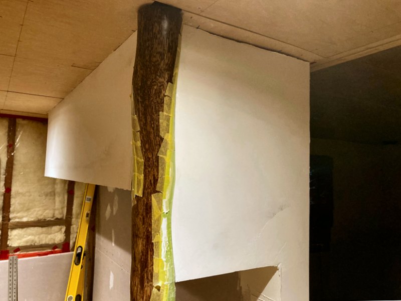
The Tokobashira Plaster Work
However, the remaining plaster work for the tokonoma walls required some attention before getting too lost in playing with
that new post. The walls themselves weren't any big deal, but the parts where the GWB met the tokobashira we're a little
odd, in that some sections were even with the edge of the post, and the post was proud of the wall plane in other sections. That meant I was filling
lots of the gaps with plenty of joint compound, then I'd need to wait for the stuff to dry overnight before doing a little clean-up and then repeating
the process. After doing this for a few days, the wall-to-post transition was starting to take shape. The trouble was that all that joint compound
will likely crack when the post expands and contracts during seasonal changes (which is what happened to the plaster around the post in the tea
house). I decided to trim back the plaster that had already been slathered on the post, then used a thin putty knife to go along all the edges
and made certain there was no plaster making any contact with the post. I then made up a bunch of "spacer shims" by folding lengths of 2-inch
wide masking tape to build up something fairly flexible to put in the gap. It worked out that six layers of tape was a decent thickness, which I then
covered with a piece of plastic packing tape to prevent the compound from sticking to the spacer. The "spacer shims" were then inserted in the
gap and held in place with yellow FrogTape®, and I got back to plasterin'. The most important part of this process was
to simply be patient — a little plaster was applied along the post, but not so much that it'd sag, and that was it for the day. The next day any
humps got sanded off, and the process was repeated. I did manage to also work on the many tokonoma wall and ceiling inside corners
while I was playin' with plaster. After a week or so of this the post edge was lookin' good, so I then put a skim coat of plaster on all the walls next
to the post, both inside and outside the toko. I didn't do any brush texture application on these walls, but did leave a few
small surface irregularities when I did the final trowel work for the glaze.
The next step was to get the walls primed, painted, and glazed. I carefully removed all the "spacer shims", and after a little very light sanding of the new plaster edge gap, I re-masked the entire tokobashira to prevent slopping any paint on the thing — all that fiddlin' with a putty knife to get the plaster off the thing the first time scratched it up a little, so it's gonna need some sanding and stain work to get it lookin' good again — I don't wanna make things worse by gettin' paint on it too. Primer, paint, and glaze application proceeded smoothly, and we're quite pleased with the way the smooth, troweled plaster finish looks with the glazes applied. This should work well for the rest of the toko walls when the time comes. Now I just needed to get that new post figured out so I could get after the living room ceiling work.
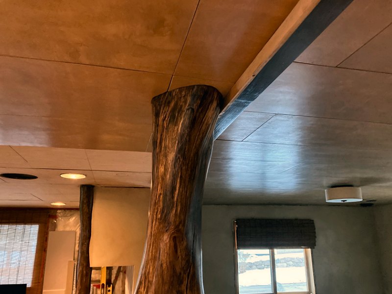
The Daikokubashira Installation Work
So what the heck is a daikokubashira? Most simply, as stated above, it is the "central pillar" of a traditional
Japanese minka residential structure. It was typically the largest post in the interior to support the main ridge beam and
other structural cross-members, and was also often the first interior pillar placed after the perimeter frame was built. This not only made this
"central pillar" structurally important, but it also came to represent Daikokutan, one of the seven gods of good
fortune that protects the house and was associated with the kitchen & hearth (hence the name daikoku-bashira).
By the mid-Edo period the daikokubashira had become less of a "central pillar" for structural purposes and more
of a decorative element as well as a bit of a status symbol. Obviously our daikokubashira is not the first pillar erected
for the house, nor is it required to hold up anything structural — but I have good place in mind to locate the thing, and I've also been saving
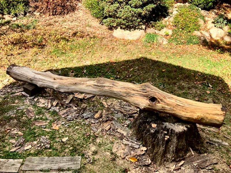
a section of Black Birch trunk to use for this thing from a tree we had to take down back in 2020.
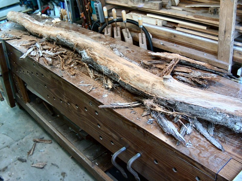
Work on the daikokubashira started with getting the 10-foot long chunk of tree trunk into a position where I could get the bark stripped off and get a look at the condition of the wood. I had leaned the thing up next to the engawa last Spring to get it off the ground and help it dry out, so now it was pushed back onto the ground, then I'd swing it around one end at a time to get it behind the green garage (I couldn't actually lift the whole thing and move it myself – it was way too heavy for that). With the big end sittin' on the old White oak stump and the other end on a wood block, I started whackin' at the bark with a claw hammer and it just fell off in chunks. The bast and cambium layers beneath the bark were just punky, rotted stuff, which was a bit worrisome. To get through the punky stuff, I grabbed the Milwaukee® 4-1/2" grinder equipped with a very coarse wire brush and that blasted away the punk to get into the sapwood, which was also pretty soft stuff. I stopped with the wire brush as soon as I could see a hint of sapwood grain, as it had already removed over an inch of punk from the perimeter of the log, and it probably could've kept going all the way into heartwood. It had also left lots of nasty marks on the still soft outer layers of sapwood. To clean things up a bit for a better assessment, I grabbed the Porter-Cable® 7" disc sander with a 36-grit disc, and went over the whole thing with that. After taking off another 1/2" or so of sapwood with the sander, I was into reasonably solid material. I had myself a 10-foot length of partially spalted Black Birch, that was roughly 8-inches in diameter. This would do the job nicely.
 Prep work & installation of the daikokubashira (7 photos).
There were still a fair number of soft sections of surface on the thing, and lots of cross-grain marks from the disc sander, so next I went over the entire thing with some 80-grit sandpaper to get rid of the really course sander marks while it was still outside. We then brought the thing into the genkan to get it out of the weather and keep it dry (removing the fairly wet bark and cambium had reduced the weight enough that I could just barely lift the thing with the help of the lovely bride). Once inside I did some measuring of the location we were intending to put it, and cut off about 16-inches of length from each end with a hand saw. That got the weight down even more, so we could move the thing into position and make some decisions about where exactly it would end up.
My original idea was to locate it on the living room side of the fusuma doors the will separate the living room from the bedroom (since that's the center line of the main room), and place it 3-feet from the bathroom wall. This would put it close to the centerline of the entryway to the main room from the genkan, align it with the 3-foot wide closet wall in the background, and leave a passageway of sorts to the bathroom when three of the four fusuma doors are closed. Nope. Luckily, my friend with the pick-up truck wandered by for a visit while we were working this out, and suggested we put the thing in the center of the 12-foot opening, rather than 3-feet to one side. Of course! The tokonoma is 6-feet wide with the tokobashira at one end, so it looked perfectly balanced to place the daikokubashira 6-feet from that, centered in the fusuma door opening. Also, when the two doors behind the couch are "closed", the daikokubashira would "define" the remaining 6-foot wide passageway to the bedroom and bathroom. Perfect. We moved the thing to the center of the opening, and then held it in place with a few shims while we shot a line on it with the laser level to get it aligned more or less plumb.
With the location worked out (and the post outline marked on the floor and ceiling), the thing went back out to the shop for more prep work. The next step was to go over the entire thing with a couple coats of Minwax® High-Performance Wood Hardener to take care of the remaining soft stuff after all that rough sanding. The resin hardener needs to pretty much go on the entire thing at once, with multiple coats over the really soft stuff until it leaves a "shiny" surface, then it needs to cure a few hours before filler application and final sanding. I thought about trying to stand the thing up in the shop for application, then hit upon the idea of making a "pillar rotisserie" rig that would let me work at the bench. A little time with some more scrap plywood and the power screw-driver, and I had my bench-top log-spinny thing ready to go (see photos above – this rig was very silly, but it worked really well). After applying nearly two jars of hardener, the entire thing was hand sanded again with 100 grit to remove the surface sheen and ready it for filler and stain. I also had to work out how to mount the thing securely, which was a bit of a challenge.
The mounting problem was that I wanted the top of the pillar tight against the ceiling "underlayment" so it would look like it "goes through" the finished ceiling panels. When I first cut the thing down to rough size lengthwise, I did my best to keep the two cuts parallel and square to the vertical centerline of the pillar. That provided a flush mounting surface for the ceiling end, but because the floor is not level, there was a significant gap on one side of the base which would not look right with finished flooring (since it should appear to "go through" the floor, too). I decided to address the base "gap" by cutting off another couple inches of pillar at the base, again trying to keep the cut level (by shooting a line around the base perimeter with the laser level), and then mount the post bottom on a small concrete "footer" that will penetrate the finished floor. The shortened post allowed me to add a small block of 4x4 pressure-treated stock to the post bottom with an 8-inch stainless-steel lag driven up through the block and into the post, then a triangle of 1/2-inch pressure-treated plywood was screwed to the bottom of the block. The OSB underlayment was removed from about a 1-foot square area at the post base, and the exposed "ears" of the plywood triangle were then screwed into the sub-floor boards with #12 stainless screws. The base whole area was then covered with plastic sheeting, and a little "post footer" was formed to match the floor slope while providing a level top for the post and filled with concrete. To secure the top of the pillar, I cut away a small section of the attic floor after some careful measuring and moved the insulation out of the way to see what was above the post. There was a ceiling joist very near the post top, so I added a chunk of 2x2 to the side of the joist with 3-inch screws, then drove a pair of 8-inch long FastenMaster® TimberLOK screws down through the 2x2 and into the pillar below. The pillar is now very solidly mounted in position, and I can finally get back to finished ceiling work for the living room.
 Ceiling panel installation work (9 photos).
Finished Ceiling Panel Installation: Winter 2024/2025
With most of the work done on the daikokubashira and tokonoma, I could finally get after installing the
stack of finished ceiling panels for the living room. There was still one last thing to address before I could start getting them up, and that was how the
panels would align with the edge of the fusuma door header (since that's the only really "straight" thing in the room).
In the bedroom, the "ceiling underlayment" was even with the top of the header, so the end of each finished panel could just butt against
the header for proper alignment. In the living room however, the "ceiling underlayment" is even with the bottom of the header, so
there's nothing to butt the finish panel against. That meant I needed to cut, finish, and install the trim board for the bottom of the header before
the panels could go up. That work only took a couple days, and I also decided to add a 1/2" thick temporary spacer along the edge of the trim
to create a little gap between the finish ceiling panel and the header trim (which will allow a 1/2" wide rabbet on the vertical header
trim to fill the gap and cover the ends of the finish ceiling panels). I also spent a little time getting the stain and a few coats of oil on the
daikokubashira and tokobashira as the first couple of panels went up.
Panel installation proceeded smoothly, albeit a bit slowly. I used the same "cheat sheet" plan I had referred to when doing the Bedroom Finished Ceiling Panels to keep track of what length panel went where, and started installing them along the header at the bathroom wall corner of the living room. My goal was to try and get one or two rows of panels up each day, as I was also still working outside on the Vanagon as weather permitted, as well as getting additional coats of oil finish applied and rubbed out on those pillars. We had planned to not install the end panel for each row along the East wall, and also skip the last row at the South wall since both those walls still need GWB installation and finish work. After getting a couple rows installed however, we decided to go ahead and get the entire finish ceiling up now — That will allow me to do all the nail putty and scuff sanding work to complete the panel installation, then I'll just need to mask off the ceiling when it comes time for GWB work.
After a few days of steady progress, all of the finished panels for the living room ceiling were installed. The project wasn't completed however, as now it was time to go over the entire thing with the Minwax® Wood Putty® for the nail holes, just as was done in the bedroom. For the living room I decided to save a little time and skip the areas that will be covered by trim — every spot needs to have two applications of putty to allow for initial shrinkage, and since we determined we were going to put trim up to cover all the panel end seams after getting the bedroom ceiling up, there's no need to apply putty to the living room ceiling spots that will be covered. Still, this was not quick work. I can only work on overhead putty application for so long before the arms turn to jelly, so getting all the nail spots covered took a few more days of work. All the putty spots were then wiped down with mineral spirits to remove the excess putty, and the whole process was repeated.
Once the final application of putty has been spot wiped with a rag, I then go over the entire ceiling with another "wash" of mineral spirits to remove the residue from the rag wiping. For this step, I use a window cleaning microfiber brush with some mineral spirits in a bucket. A quick wipe with the brush thing, and all streaks are removed. I then go over the whole area with a dry towel, turning it often, as final clean-up. The last step is to then go over all the panels with a Scotch-Brite® woven, abrasive pad mounted on a drywall pole-sander to knock back the gloss of the finish a bit, again, just as was done on the bedroom ceiling panels, followed by more towel work to remove any sanding dust. I then installed all the recessed light trim rings, H.R.V. supply vent, and the last smoke/CO detector near the bathroom entrance. The living room is ready for the last of the GWB work!
 Building the new light started with a simple plan (3 images).
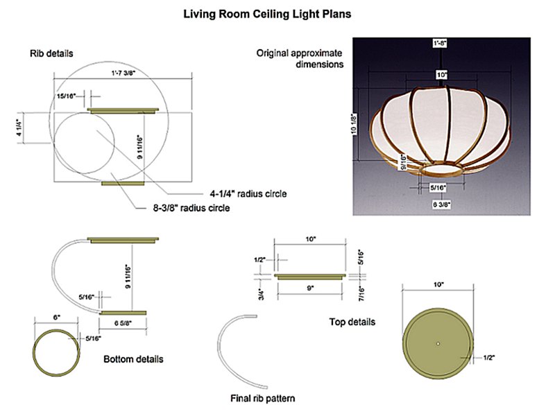
The Main Ceiling Light: Late Winter 2024/2025
One thing that's been bothering me for a while as the living room work has been progressing, is what to do about getting a "proper" ceiling
light for the space. When I was getting the wiring taken care of for the living room ceiling, we added a box for the ceiling light, then just
tossed in a temporary standard bulb holder and hung an IKEA® paper lantern on it to do the job at the time. That thing is
by no means what we want for a final fixture, so the search for a fixture began in earnest back in 2023 when the wiring was done (and when we
purchased the drum style flush-mount fixture for the bedroom ceiling). At that time, we also purchased a knock-off copy of the 1952 George Nelson
designed "saucer bubble" pendant lamp, which will work to replace that IKEA® thing now that the finished ceiling
panels are up. What I really wanted to find however, turned out to already be shown on the KesterHouse site in that first photo of the
Interior Design section of the main Interior page – a wood-framed,
"pumpkin-style" paper lantern. After lots more searching, I finally tried a Google image search with that photo, with promising results.
Unfortunately, most of the results were from Amazon.jp, which makes buying the thing rather difficult in the U.S.. I then finally managed
to find the Japanese company that actually manufactures the lamps, a company called Miura
Shomei Co., Ltd.![]() , founded in 1890 in Kyoto.
It may be possible to work out some means of getting them to sell me a lamp (the closest match appears to be their "New Semi-circular"
pendant, item MP-17). It costs over $800, and that doesn't include getting the thing shipped to the other side of the planet – if they'd
even do that. I'm not going to bother them with my silly request to get one.
, founded in 1890 in Kyoto.
It may be possible to work out some means of getting them to sell me a lamp (the closest match appears to be their "New Semi-circular"
pendant, item MP-17). It costs over $800, and that doesn't include getting the thing shipped to the other side of the planet – if they'd
even do that. I'm not going to bother them with my silly request to get one.
So, having found the exact lamp we wanted, I decided to attempt to make the thing myself. I have no intention of making and selling these things, so hopefully the folks at Miura Shomei won't get upset if I try to copy their fine work (if I thought there was any chance of getting the lamp from them, and not just ending up with a box of broken sticks and torn paper, that would certainly be easier than making the thing from scratch). My first notion to build it was to not try to cut those 12 outer, half-ring support rib things from solid wood (which is what they do, using Akita Cedar), but instead I figured an easier way to make them consistently would be to laminate each piece from thin wood, glued up in a form. I could just make one form, then glue-up one rib at a time while working on other projects too.
As usual, I started the task by creating a plan from which to work. With known dimensions of 500mm by 240mm from the Miura Shomei product listing (so basically 19-5/8" by 9-7/8", which I bumped to 20" by 10"), I grabbed the image from their site and dropped it into the plan sheet, then re-sized it until the dimensions were about right. While working on the plan sheet, I also ordered a package of 1/16" thick Poplar veneer from E-Bay to use as the stock for the laminated ribs and bottom ring. From the dimensions on the plan, it was looking like building up the rib laminates to 5/16" thickness would do the job nicely (so five pieces of veneer per rib). It looks like I may need to also steam the strips a bit to make them bend easier, which means I'll need to steam and bend the stock for each rib, then let it dry overnight in the form before gluing it together (or perhaps I can make two forms – one for glue-up, and one for pre-bending. We'll see…) I'm planning to use Titebond® "Genuine Hide Glue" for the assembly, since it doesn't leave a visible glue line for finish stain, and has a long open time for making each glue-up. Time to make those forms and get the strips ready.
A Little Living Room Ceiling Trim Work: Fall 2025
Most of the focus for interior work so far this year has been on getting the bedroom trim and flooring work completed in order to assemble the
bedroom furniture before the holidays. That will allow all the furniture boxes currently stacked in the living room to go away, which
then lets us get at the living room walls for the last of the GWB work. By mid-October the Bedroom
Ceiling Trim work was completed, however before undertaking the installation of the flooring in there, I decided to make a little headway
on the living room ceiling trim (since all the trim stock was already inside as I'd been working on the bedroom for the last few weeks).
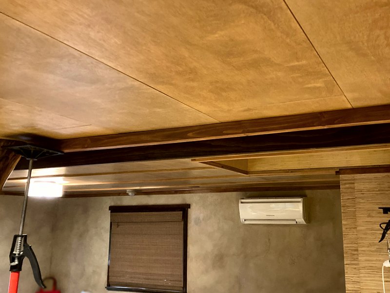 Fitting the header/ceiling trim for the living room (9 photos).
Specifically, I wanted to take care of the ceiling trim along the living room side of the fusuma door header, since that was the last thing I'd done to complete the bedroom ceiling trim and was kinda "on a roll". As mentioned above, the ceiling panels for the living room were installed even with the bottom of the door header trim, with a half-inch spacer/gap between the panel and the bottom header trim board. That means there's really nothing to support the side trim for the header on the living room side (the ceiling is higher in the bedroom, so the side trim attached to the side of the header in there). To make this work, I determined I'd first need to get the mawaribuchi perimeter trim boards installed along the header (offset 3/4" from the header bottom trim), then attach the header side trim boards to the mawaribuchi from the header side. That also meant I'd need to cut away some material from the top of the daikokubashira post to accept the end of the mawaribuchi. This was gonna get a bit tricky…
The first thing to do was mill a short piece of 3/4" stock that was 3-1/4" wide to match the bedroom header trim (and cover the door track and rollers when those go in), and had a little 3/16" deep rabbet at the top to fill that 1/2" wide gap between the ceiling panels and the header bottom trim. I could then slide that test-fit piece along the gap to check for interference with the post – which needed a bit shaved off to keep the 3-1/4" piece plumb. With that piece then held in position, I added a short piece of ceiling perimeter trim next to it to mark what needed to be removed from the post for that perimeter trim to fit into the post. The ceiling trim doesn't actually go through the post (since that little area will be completely hidden by the header side trim), so the same process was repeated for the ceiling trim piece on the other side of the post that runs from the post to the tokonoma end wall, again cutting a notch on that side of the post to fit the end of the ceiling trim. I then cut a couple finished pieces of mawaribuchi stock to run from the wall on each end of the header to within the notches in the daikokubashira and attached those with the 15 ga. finish nailer.
With those two pieces of mawaribuchi now installed, I went ahead and put in the saobuchi pieces to cover the first living room ceiling panel seam, which is within a few inches of the header. Those two pieces also required some test fitting to mark and cut notches in the top of the daikokubashira for them to fit in to, just like had been done with the perimeter trim. While workin' on the post for the ceiling trim, I also spent some time getting a couple coats of stain, then a few coats of Minwax® Polycrylic™ clear coat on the stock for the header side trim. After a few days, everything was ready for installation. To get the side trim attached I used the 2-inch brad nailer, and nailed the stuff up from within the door track space. I then had to sink each brad with a nail set by hand, since the angle left the head stickin' out about 1/8". A few more days to get all the putty applied and cleaned up for the nail holes, and the header trim was completed. Time to get back to workin' on the bedroom (and perhaps put a little time into that ceiling light project too).
Living Room GWB Installation: Late Fall 2025
After spending some time working on the Bedroom Floors and floor trim work, then building all the
New Bedroom Furniture (so all those IKEA® furniture boxes went
away after tripping over those for five years), we were finally able to get the living room cleared out enough to tackle the last of the
Gypsum Wall Board (GWB) work for the East and South walls of the living room. I had saved a handful of larger 4-foot wide cut-offs
of GWB from when we did that work in the bedroom last Summer, which should be enough material to do the areas above and below the living room
windows, so I picked up four more sheets of the USG Sheetrock® UltraLight Gypsum Base Imperial®
stuff for the rest of those two walls, and got things started.
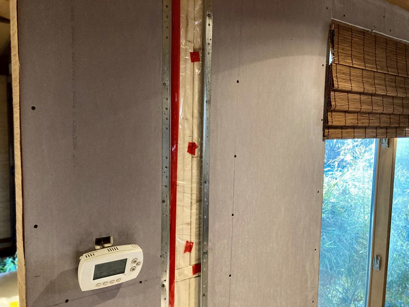 The last bit of GWB installation for the living room (6 photos).
Installation began with the first roughly 4-foot wide section between the entryway to the living room from the genkan and the East window, but this section also needed a little rough carpentry to work out a "problem" I've had on my mind for a while now… I've been trying to stick with an interior wall finish "rule" we came up with years ago when interior finish work began, which is that all interior wall finishes for the exterior facing perimeter walls would be textured plaster with a paint and multi-color glazed finish, while any interior partition walls would be finished with grasscloth wall paper. That's worked out very well so far as all the interior walls are perpendicular to the perimeter walls, so there's a "trim-able" transition from wall paper to plaster (the exception to this "rule" is the interior walls of the tokonoma, which will not be wall papered as that would be just plain wrong). The problem for me has been how to deal with this little "partition wall" section of the East living room wall that sticks about 14-inches into the entryway from the genkan. That section should get wall paper, but then the rest of the wall should get plaster and paint. The simple solution would just be to put the GWB across the entire wall, then wall paper the left, 14-inch wide partition section, paint everything else, and then slap up a piece of 3/4" thick trim when it's done and call it good. I think that would look like a poor solution that was installed as a bit of an afterthought when doing trim carpentry, so I wanted to come up with something better.
My solution was to add a couple of 2x3 studs within the existing framing to provide support for a more substantial vertical trim piece, and also provide an attachment point for the GWB to terminate on both sides of that trim piece (instead of just the edge of a single stud that was at that point in the wall initially). Those new studs will allow me to install a stout 5/4 trim piece that will appear as the end "post" of the South facing genkan wall that pierces the East living room wall, and create a distinct separation between the little 14-inch partition wall on the left and the start of the plastered living room walls on the right. The GWB also got a piece of metal corner bead on each side of the new vertical trim space, that will allow a little gap between the wall finish surfaces and the vertical trim to further emulate two distinct wall sections when it's all done. The photos here should help make clear what I'm talking about.
With that little partition wall business worked out, the rest of the GWB for the East wall went up without issues. Once I reached the corner and could get started on the South wall work, I needed to carefully document the locations for stuff that may get installed in that South wall eventually – that being the measurements for future in-wall speakers. When I re-organized all the audio and data wiring below the South wall window for the entertainment center a couple years ago, I also added the wiring for a couple of in-wall speakers in case we decide to get rid of our floor standing speakers some day. Now that I have a level, finished ceiling installed, and with GWB on the East wall (to provide a good surface from which to measure), I could record the measurements for the in-wall speaker locations on each side of the window, as well as the two horizontal framing pieces that will support the chigidana shelves at the end of the tokonoma on the right side of the window.
The exact dimensions for the left side speaker opening are 37-3/4" from the finished ceiling panel to the top of the opening, and 56" to the bottom of the opening (where there is a horizontal piece of rigid foam between the wall studs at top and bottom); and then 12-1/2" from the East wall GWB surface to the inside of the opening's left side vertical stud, and 27-3/8" to the right side vertical stud. The right side speaker opening is 38-1/4" from the finished ceiling panel to the top of the opening, and 56-1/2" to the bottom of the opening; and then 22-1/4" from the tokonoma back wall GWB to the inside of the opening's left side vertical stud, and 8-3/4" to the right side vertical stud. That leaves an area that's 18-1/4" tall by 14-7/8" wide on the left opening, and 18-1/4" tall by 13-1/2" wide on the right opening (which means we could fit even the large THX® Certified Select, Monoprice Monolith® 2-way speakers in there – but not the 3-ways without cutting into the vertical stud on the right side opening). The horizontal wall framing to support the chigidana shelves are a couple chunks of 2 x 4 that are nailed in-between the vertical studs on the right side of the window, with the upper shelf support centered and level at 28-3/4" from the finished ceiling panels, and the lower shelf support centered and level at 35-1/4" from the ceiling. The upper support's horizontal position starts with the vertical stud that's 6-3/4" from the tokonoma back wall GWB and continues between the studs all the way to the window rough opening framing. The lower shelf horizontal support runs between the two studs, again starting with the one that's 6-3/4" from the tokonoma back wall GWB and stopping at next wall stud between the window and toko at 23-3/4" from the tokonoma back wall GWB. There's also an angled wall corner brace that can take another shelf support at the same distance from the ceiling, and 5-1/4" from the tokonoma back wall GWB.
So, with all those measurements recorded, I then blasted through the last couple sheets of GWB for the South wall without any problems. The old cut-offs that I had saved for below the window took a bit of careful measuring and cutting to get all the openings for wall boxes just right, but even that fussy work moved along quickly. With that completed, I'm very pleased to report the last of the GWB installation work for the entire house is finished!
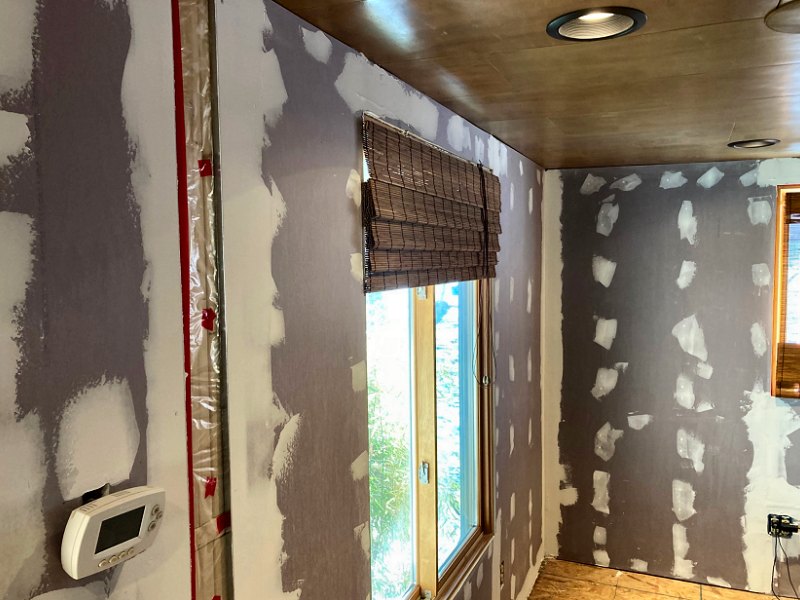 Plaster work gets underway for the living room (7 photos).
Living Room Walls Plaster Work: Early Winter 2025/26
As soon as the last of the GWB was up, I got after the plaster work for the East and South walls. I had an extra bucket of joint compound from when
I was doing the plaster work for the bedroom and closet/laundry room last Summer, so I opened that and got started. Just as I've done for
all the other interior spaces, work began with the 4-inch and 6-inch putty knives to cover all the screw heads, then hit all the seams with
mesh fiber tape, and the two corners with paper tape (so technically a "Level 2" finish). After that first application cured
overnight, the next day everything got a light sanding with a 120-grit sanding screen attached to the vacuum cleaner, then the first
"skim coat" of mud went over the East wall with the 8-inch knife (which is a "Level 3" finish, since it represents the second coat
of mud over the seams and fasteners, although in my case this second coat is spread over almost the entire surface, not just the seams and
fasteners). This process is repeated over a few more days, that is to say I'd start the task by vacuum sanding any ridges or knife tracks
off the previous day's application (specified as "surface shall be smooth and free of tool marks" for the Level 3, 4, and 5
finishes), although I don't do much sanding, as the result I want when I'm done is to actually have some unevenness and tool marks from
troweling for the when the glazes are applied. I then skim coat the next section to work my way around the room until I get to the inside surfaces
for the tokonoma walls and ceiling. Once everything for the East and South walls has gotten the first skim coat and some sanding,
I go over everything again with the a final full coat applied with the 12-inch knife and the trowels to reach a "Level 4" finish by having three
coats of mud over all seams and fasteners, although it's not sanded perfectly smooth and still has a few tool marks for when the texture coat goes on.
The inside surfaces of the toko get compound applied with a little more care, as the goal for these surfaces is to actually make them a "Level 5" finish that's almost completely free of tool marks – I just leave a few "hints" of the trowel work here and there for when the glazes go on, and these walls get no texture applied at all (although the ceiling will get some texture work to match the other GWB ceilings throughout the house).
I did one additional task, or at least an "out-of-order" task, for these walls compared to how things proceeded for the bedroom and closet/laundry room before starting texture and paint work, and that was to address the jamb extensions for the two living room windows. For other rooms I had added the jamb extensions after all the wall paint work was completed, which usually resulted in needing to do a fair amount of touch-up paint as I'd often catch a bit of paint or plaster when planing the jamb extension flush with the wall surfaces around the window. For the living room I decided to instead install the extensions before doing any primer and paint work, which should eliminate the need to re-paint anything around the windows when getting them ready for finish carpentry work. I began by milling a few of the left over strips of the original door trim stock down to be 11/16" wide and a 1/2" thick. This stock then needed to be glued to the top and side window jambs (the bottom jamb will later get a 1-5/8" wide, 3/4" thick extension added to make a proper sill), which is no simple task as there's no way to clamp the stock in position while gluing. For the bedroom and closet windows I had attached the extension stock with glue and a handful of 1-1/4" screws to hold things in place while the glue cured. The result of that was that I needed to fiddle around with some wood putty for the screw holes before I could get the trim installed, as a few of them were still visible when I went to install the trim (which is off set from the inside of the jamb surface by 1/4", so the marks from the screw heads could be seen in a couple spots). For the living room extensions I decided to try holding them in place with brads from the nail gun, as those nail holes would certainly be covered by the window trim later, but that still left the issue of having brads embedded in the jamb extensions, which would prevent later planing them flush with the wall surfaces. My solution was to cut-up a bunch of little pieces of 1/4" plywood scraps, then drive the brads through the plywood when gluing up the jamb extensions. When the glue had cured, I could then just lift off the scrap plywood pieces, and then use pliers to pull the exposed brads out of the jamb extensions. It worked very well, and of course I finally figured this out on the last two windows on which I'll ever need to add jamb extensions. Oh well. With that, the space was ready for wall finish work, which will most likely get underway in early 2026 after a little holiday break
More photos and updates to follow as work progresses…
↑
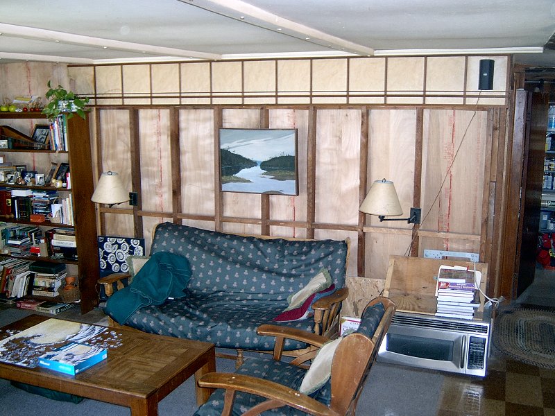
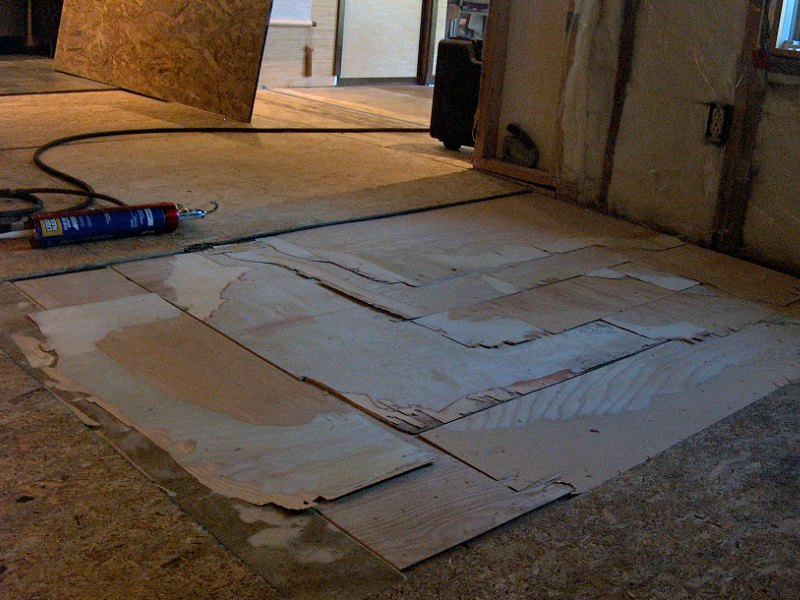
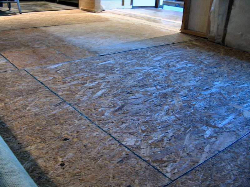
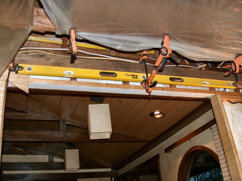
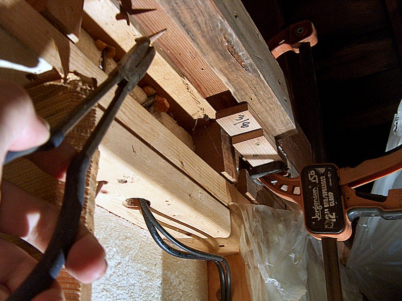
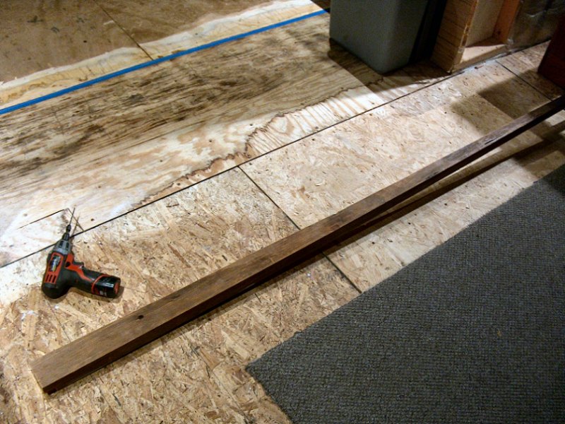
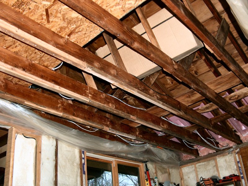
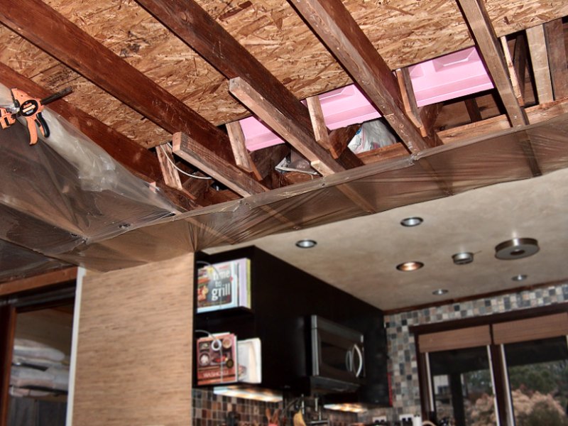
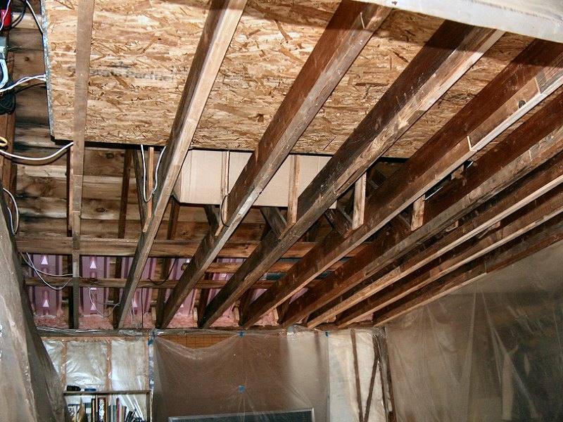
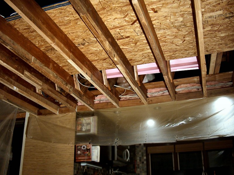
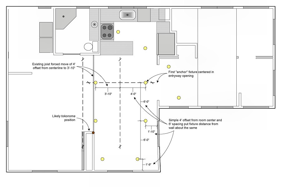
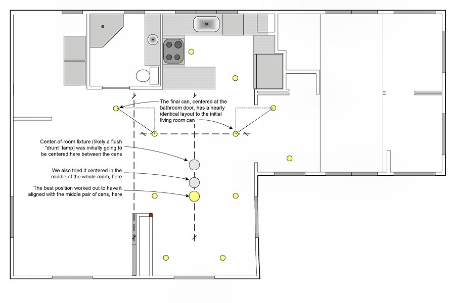
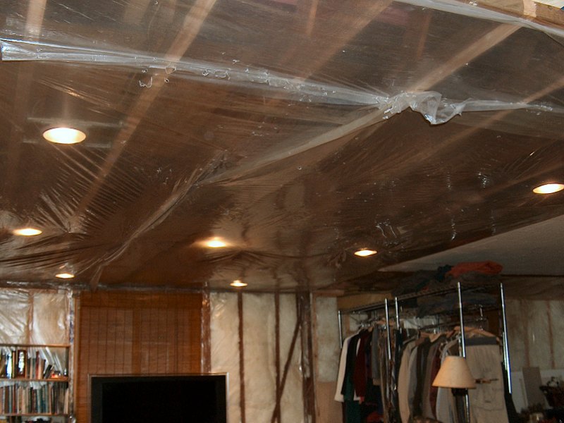
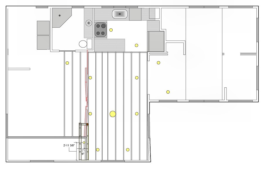
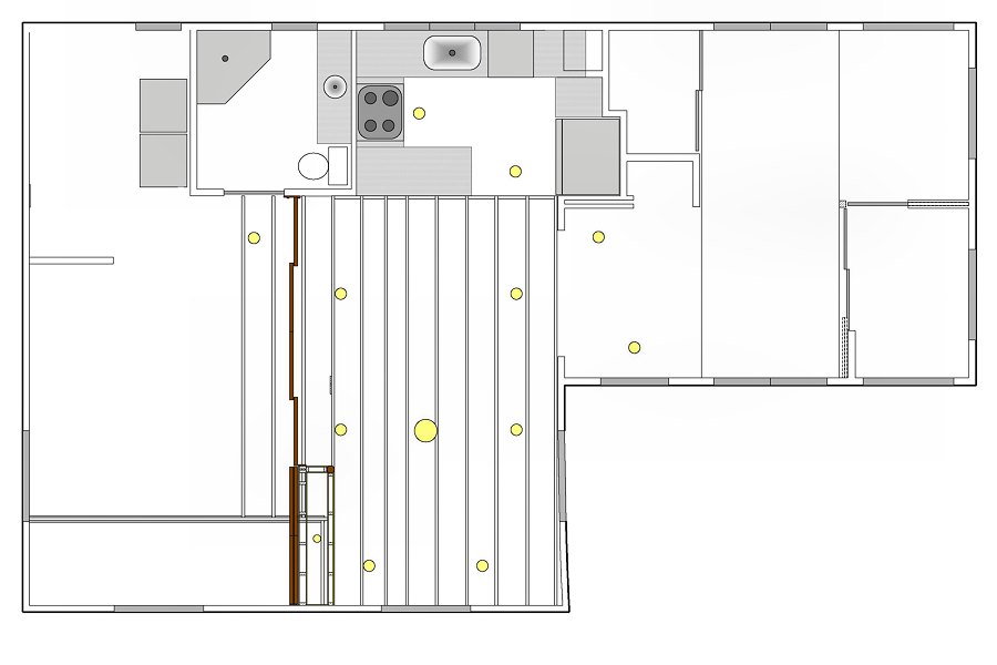
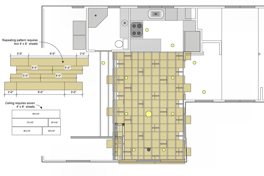
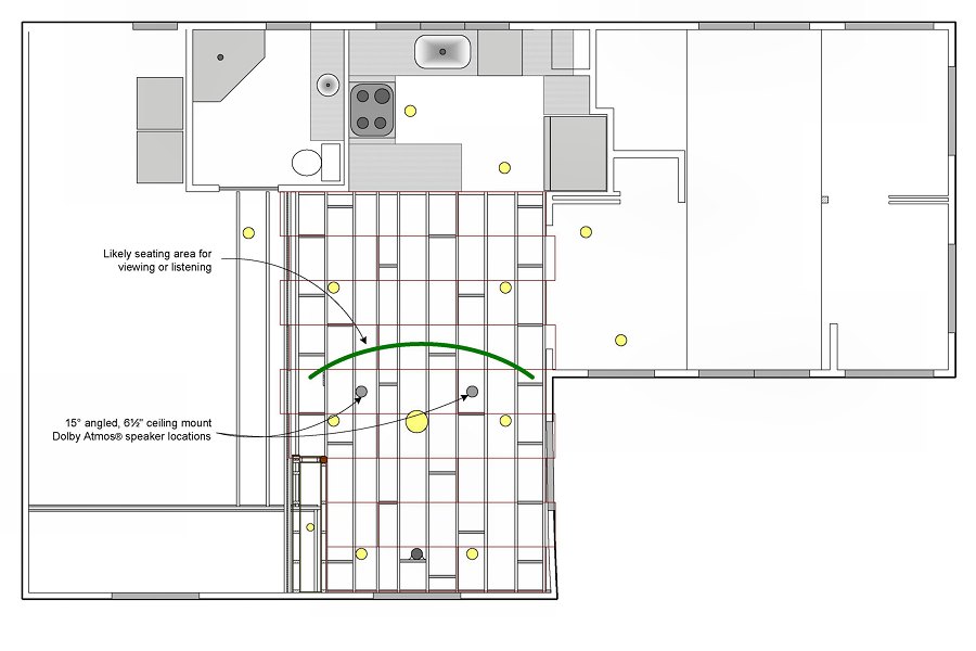
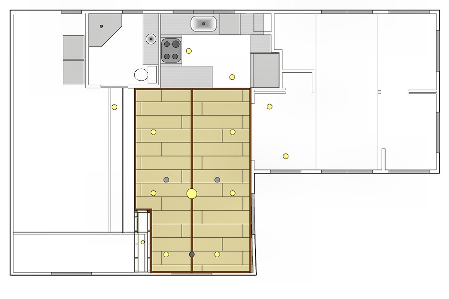
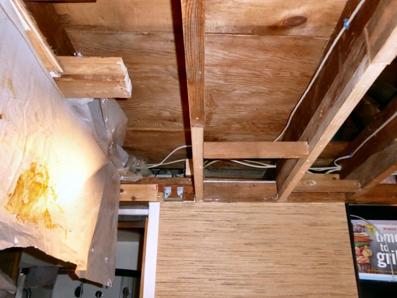
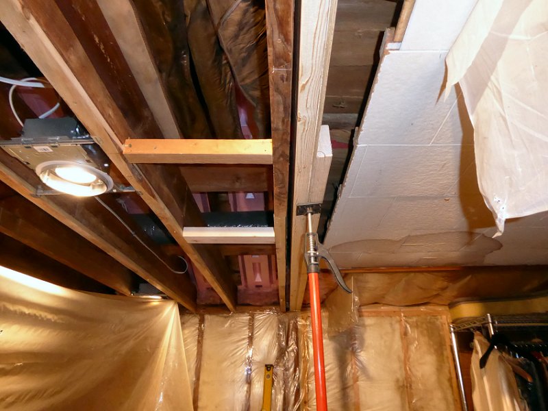
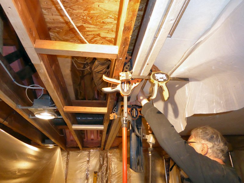
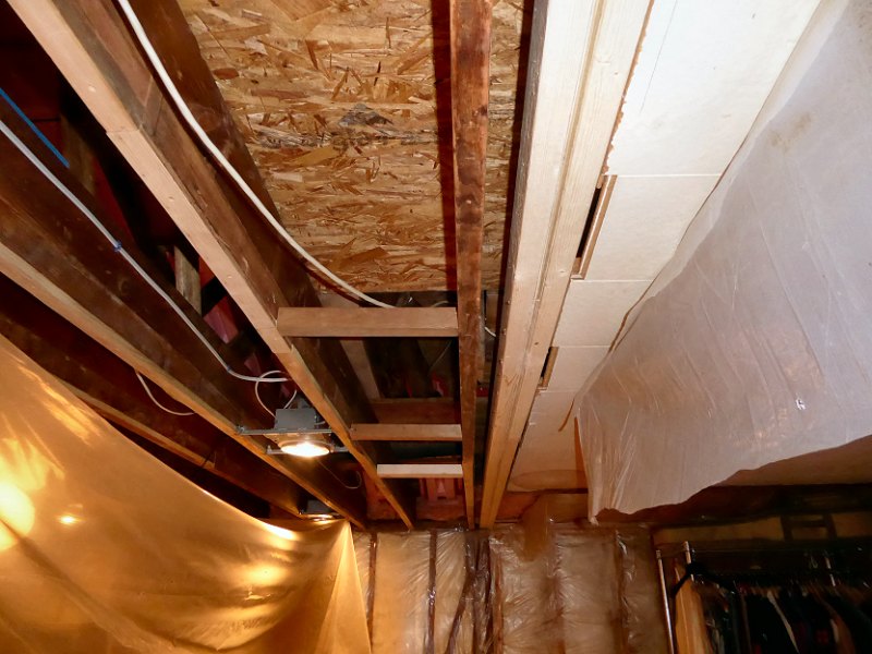
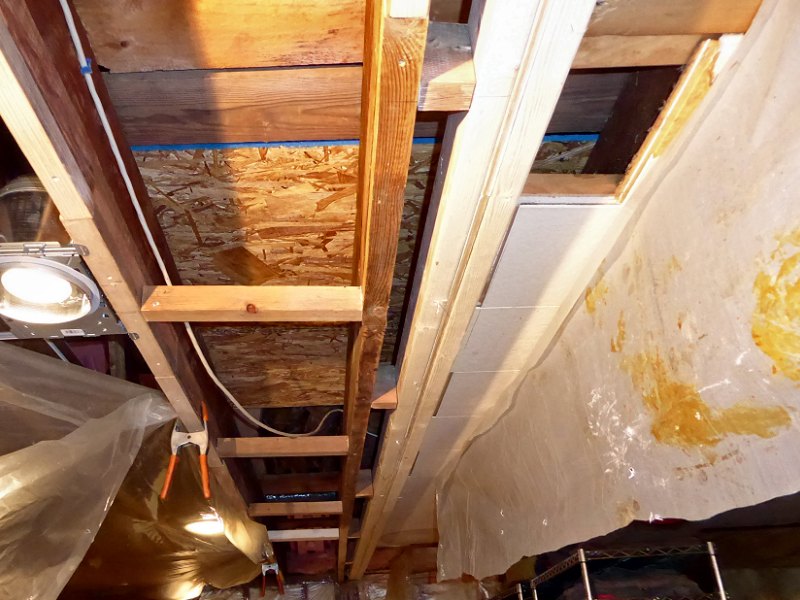
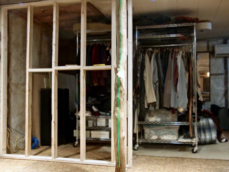
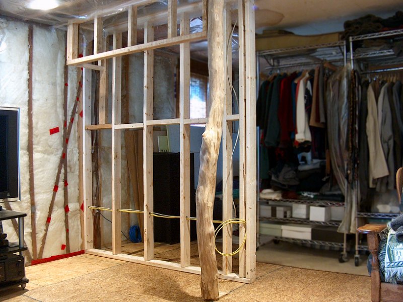
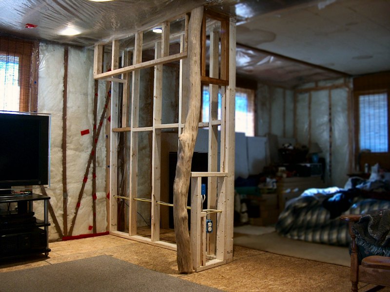
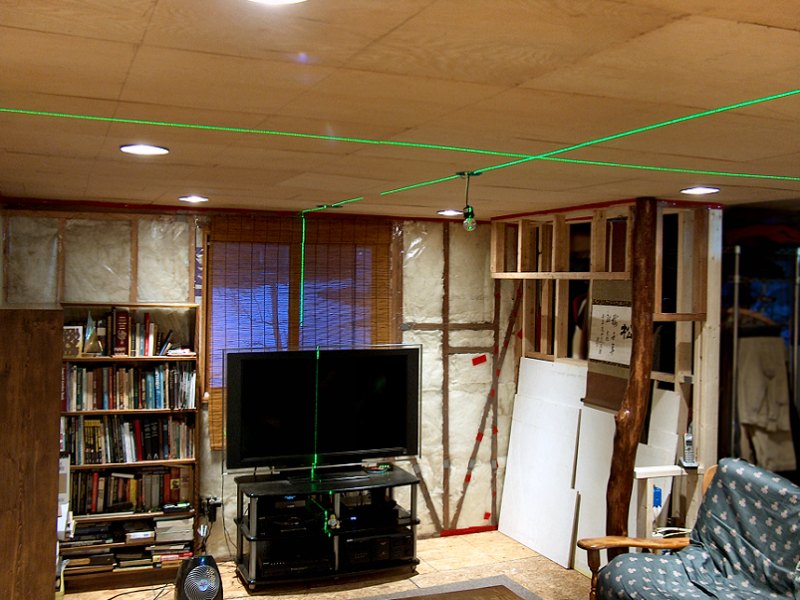
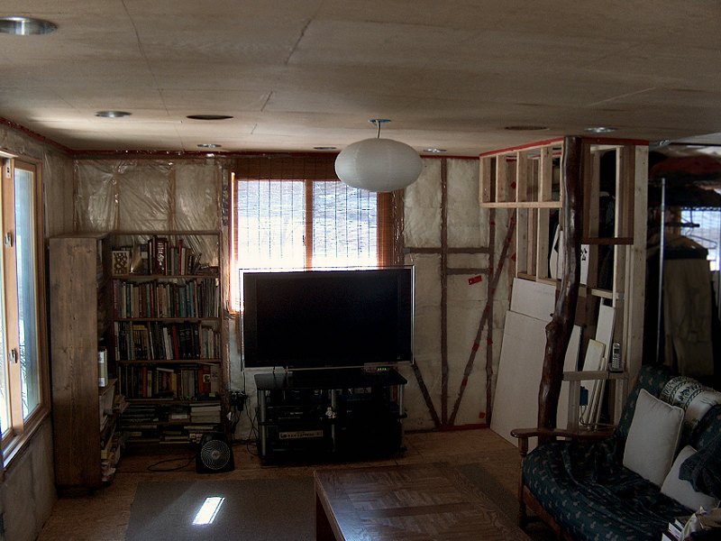
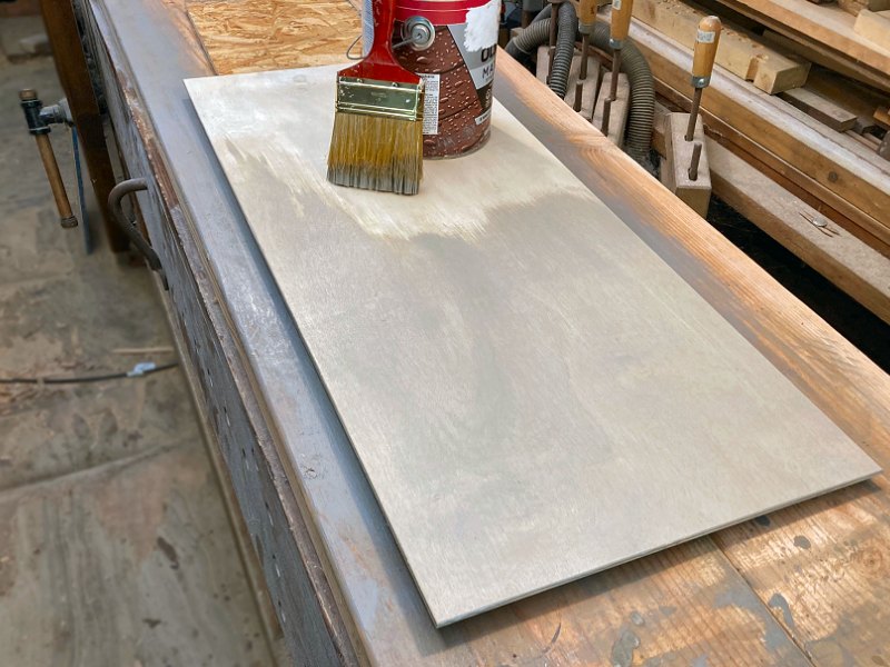
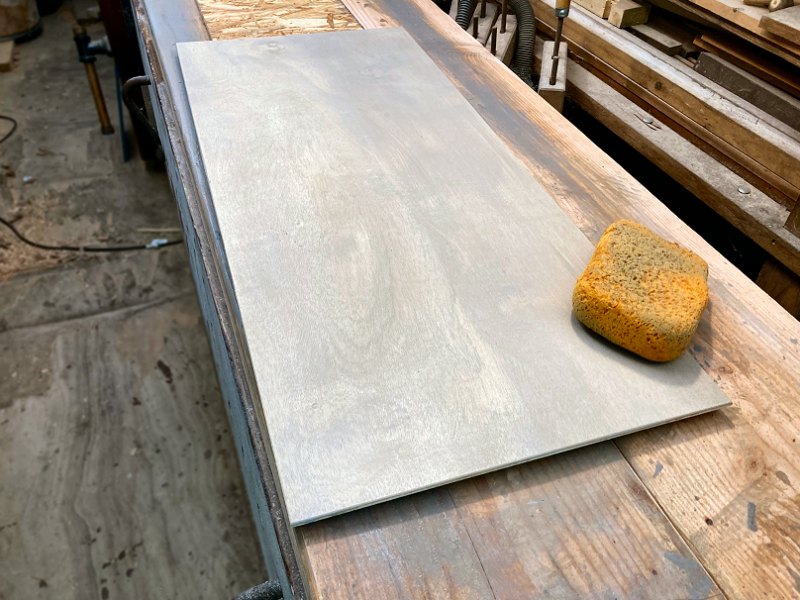
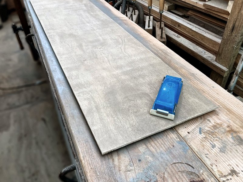
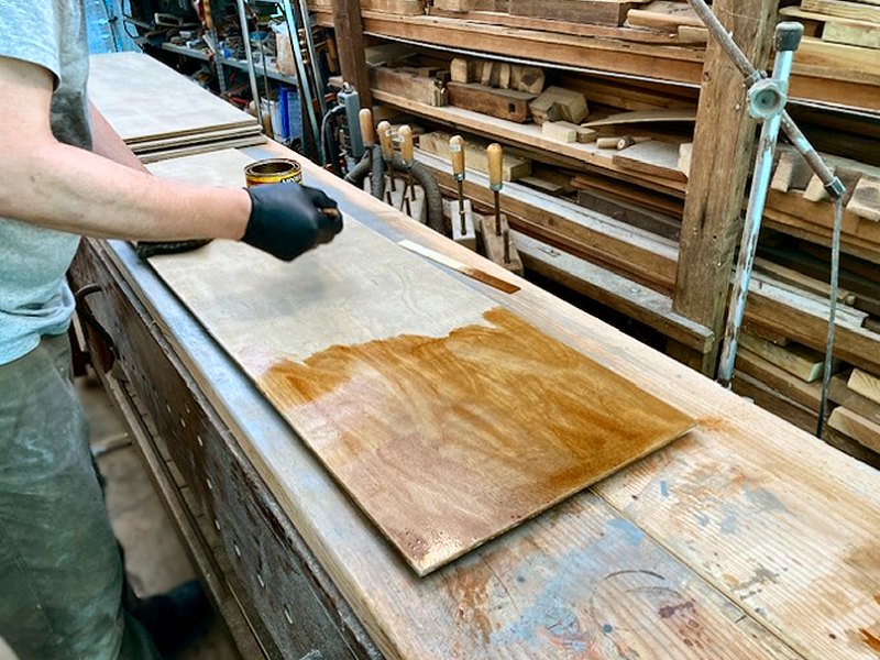
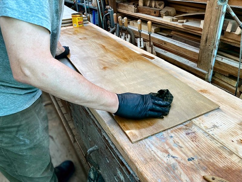
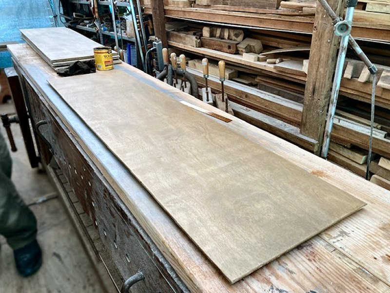
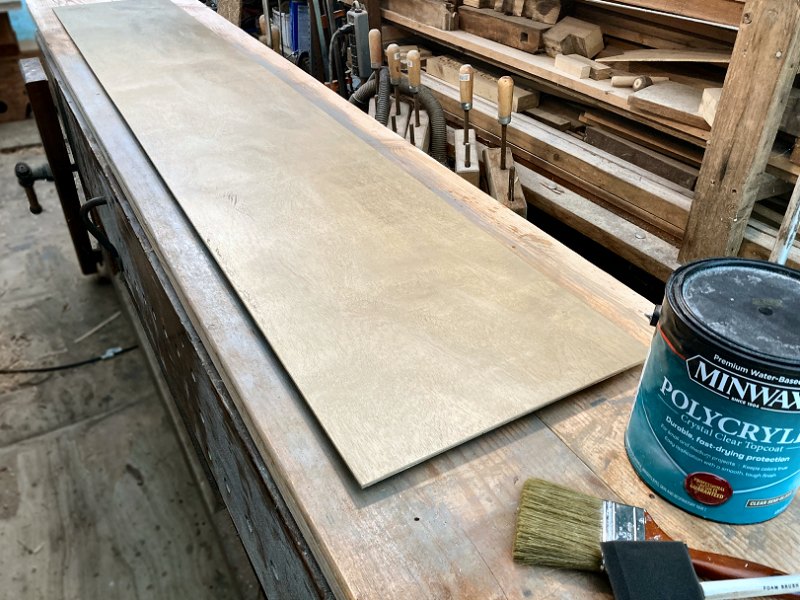
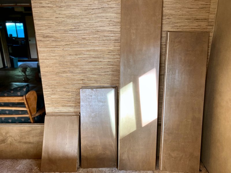
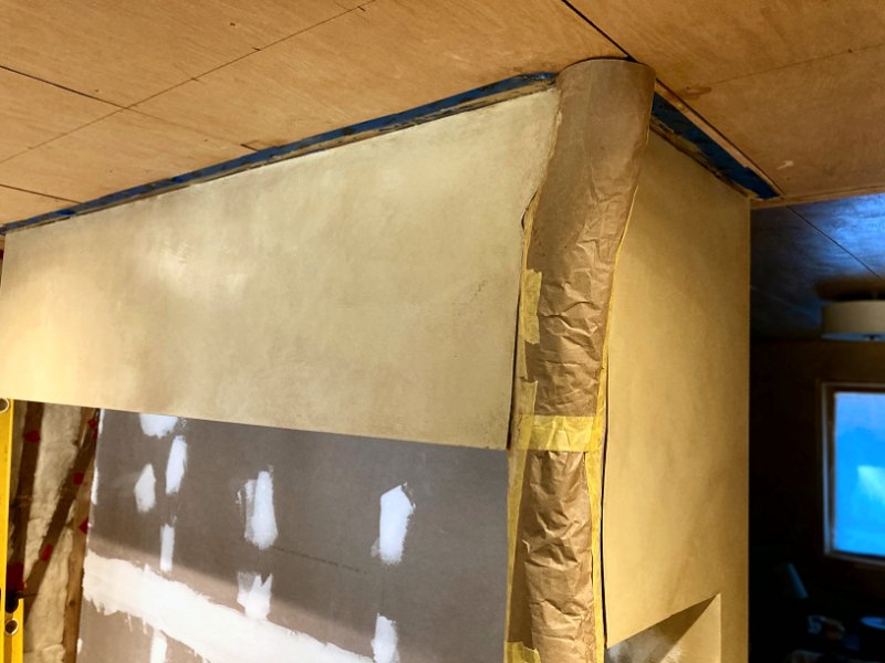
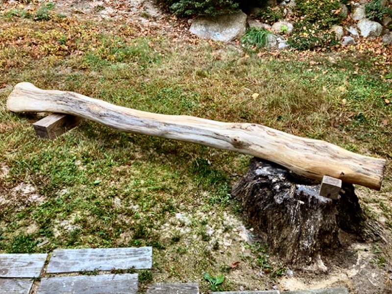
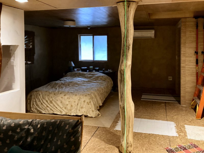
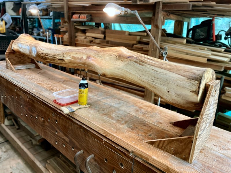
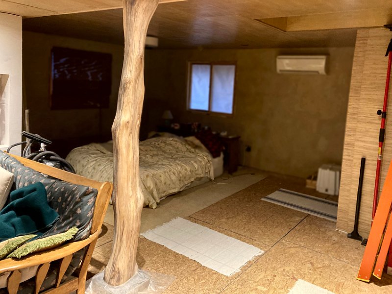
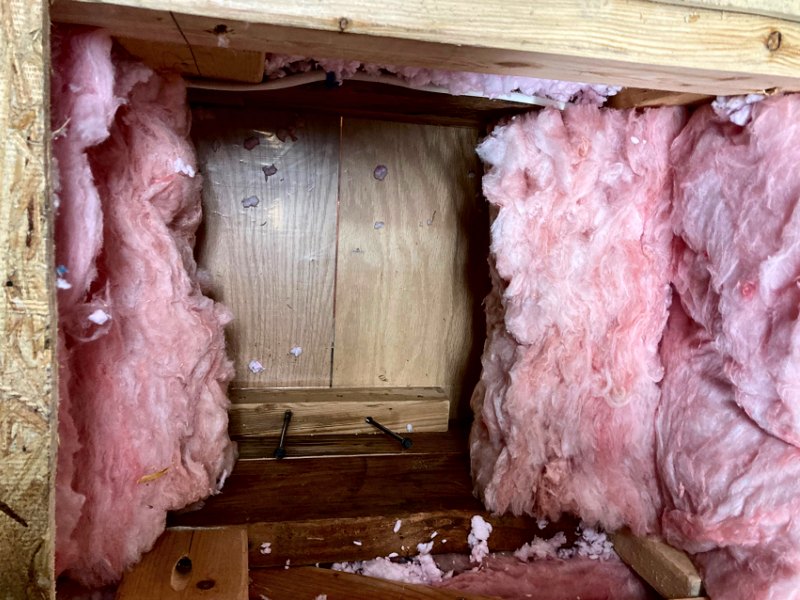
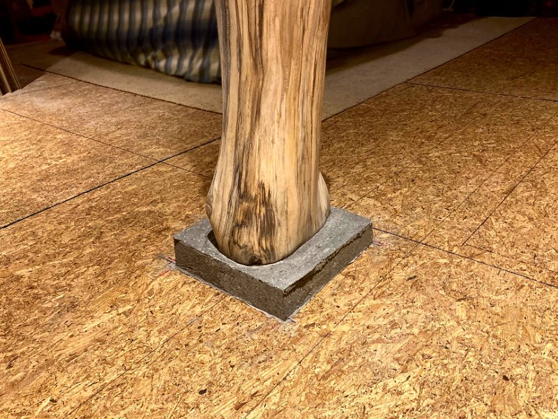
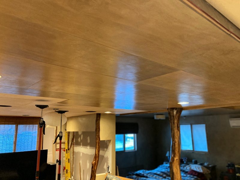
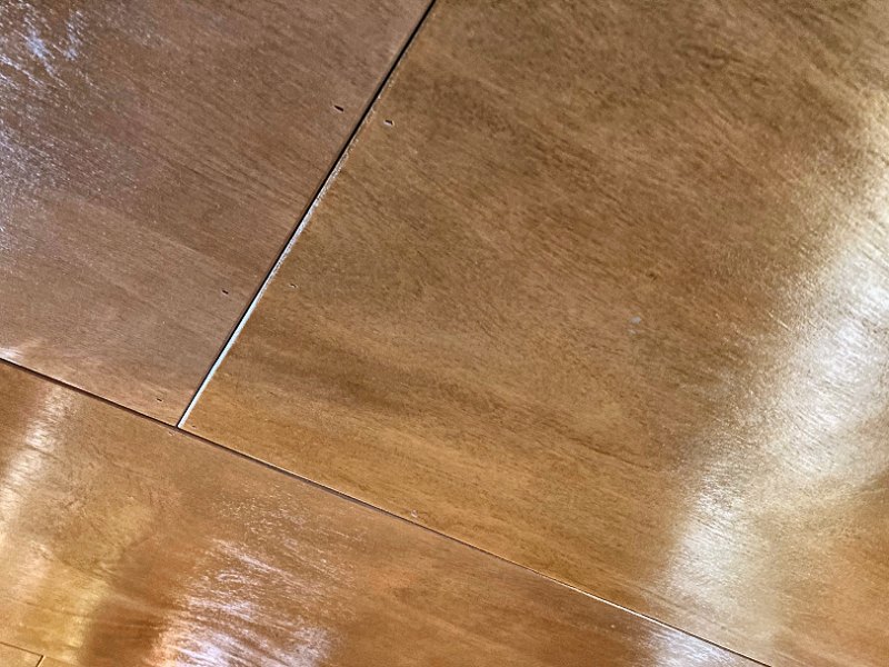
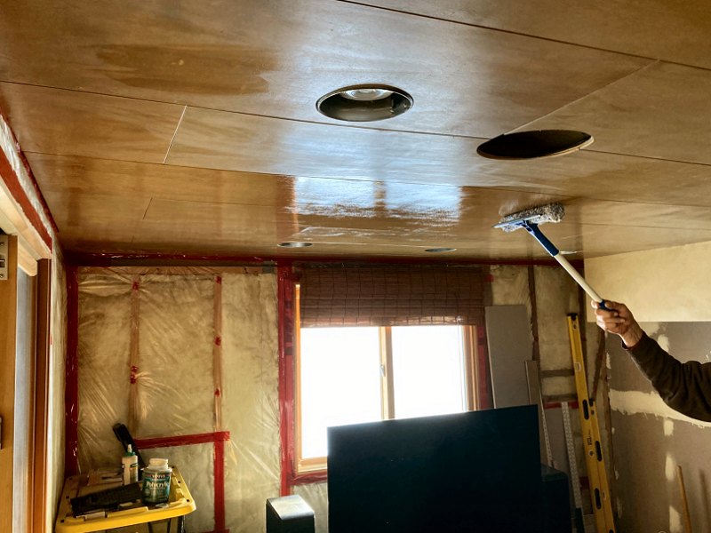
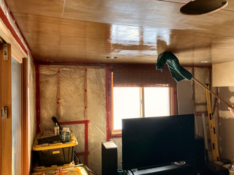
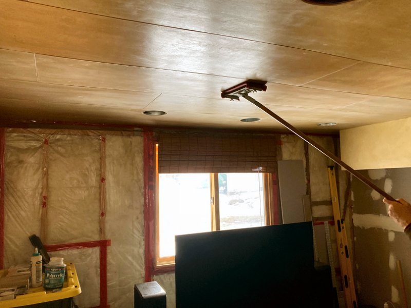
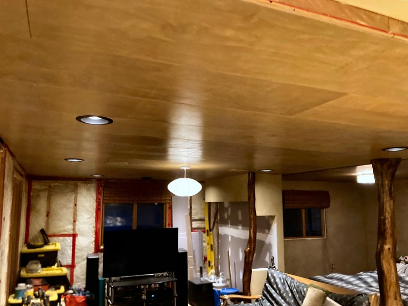
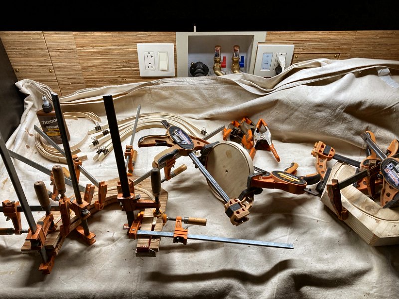
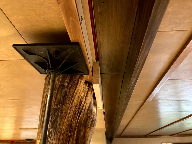
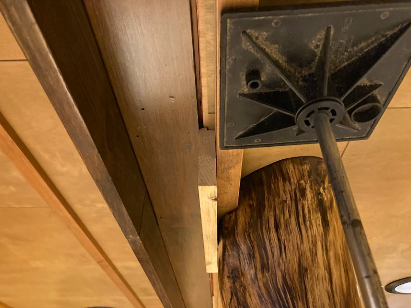
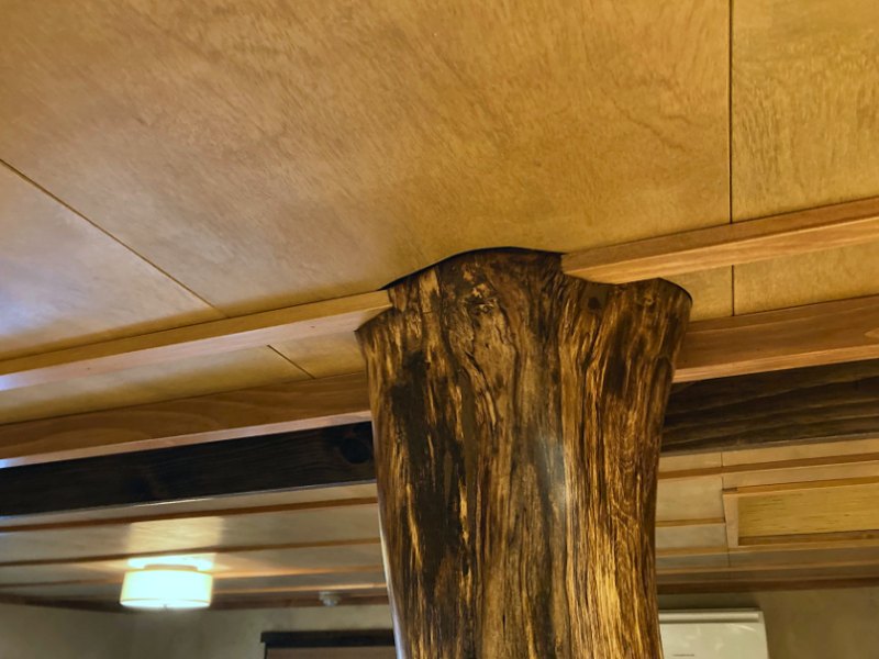
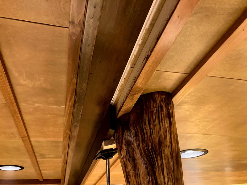
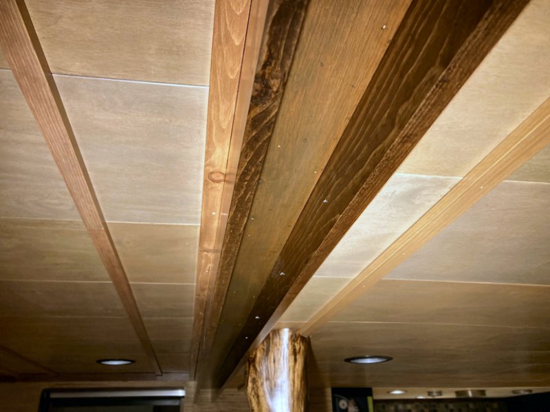
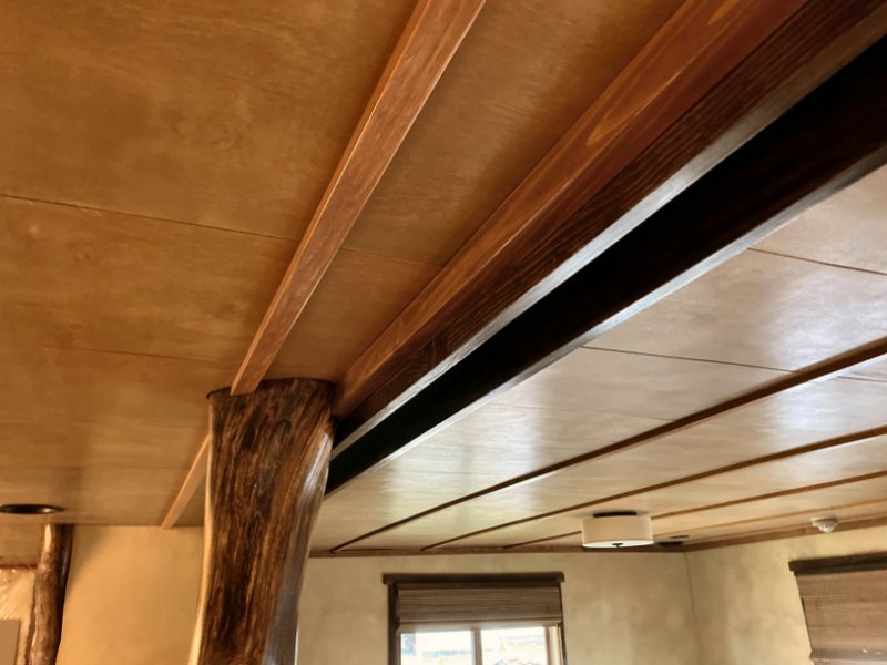
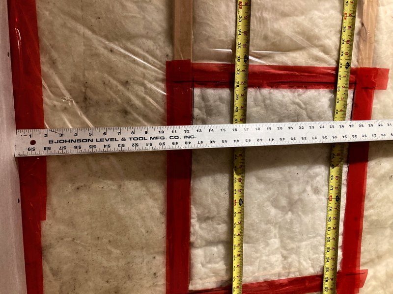
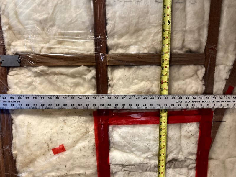
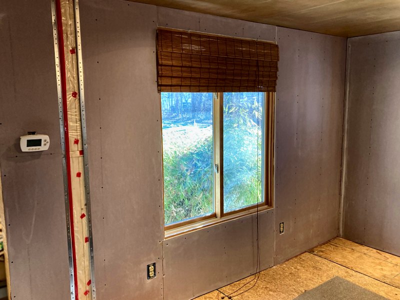
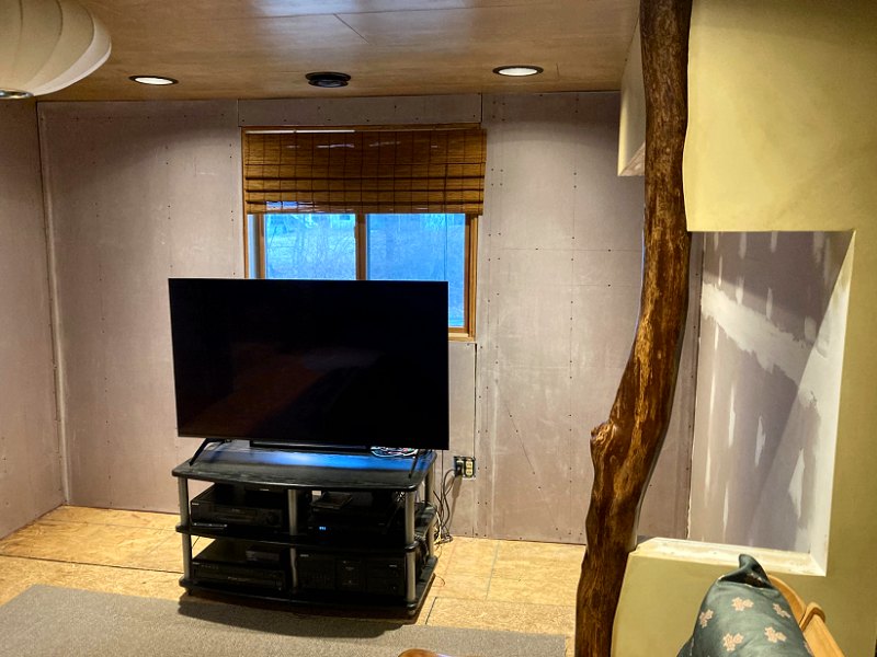
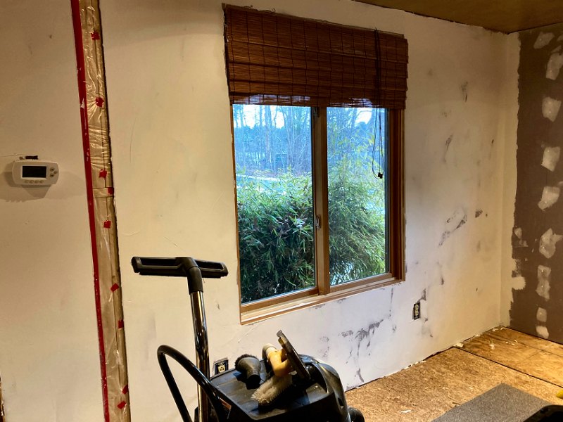
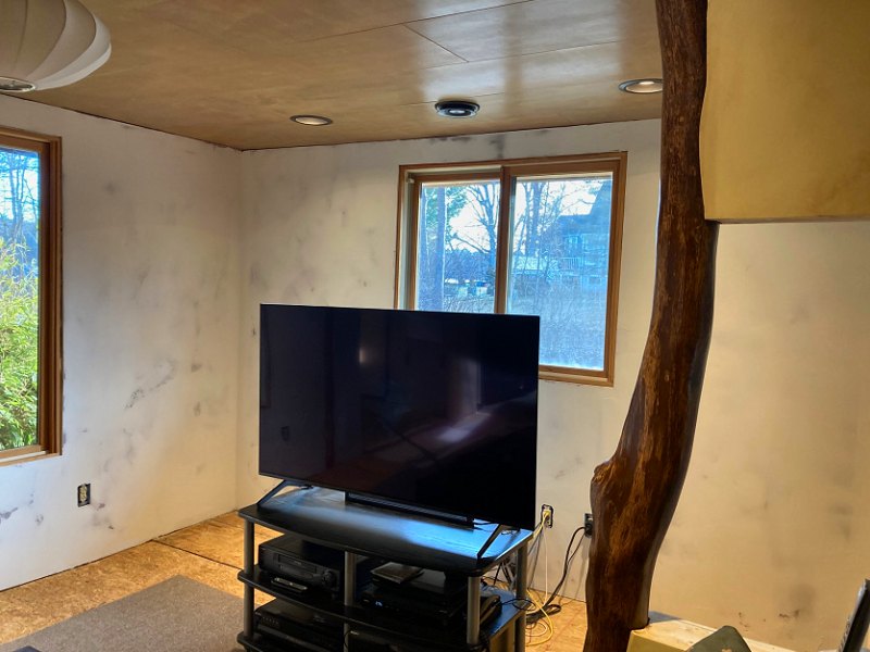
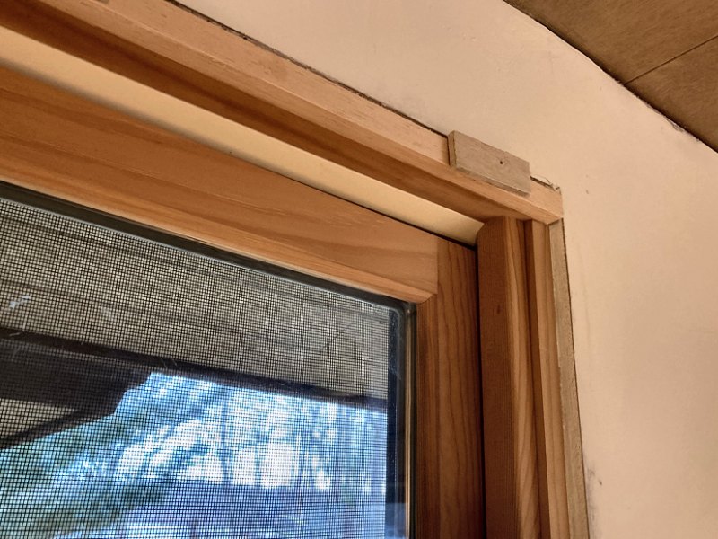
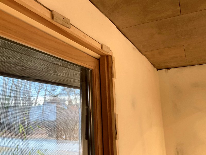
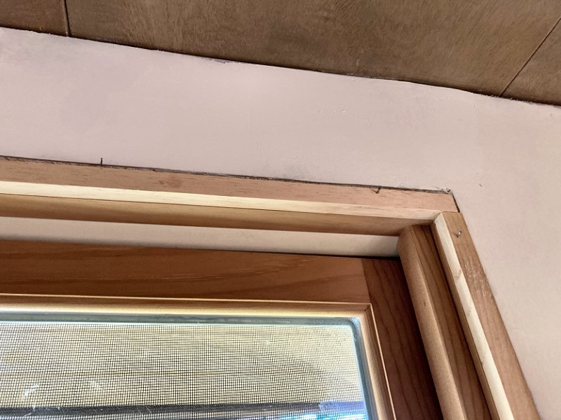
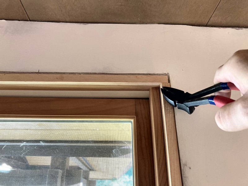